GD82559ER — Networking Silicon
58
Datasheet
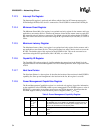
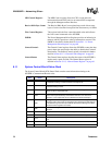
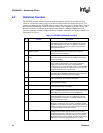
MDI Control Register:
The MDI Control register allows the CPU to read and write
information from the PHY unit (or an external PHY component)
through the Management Data Interface.
Receive DMA Byte Count:
The Receive DMA Byte Count register keeps track of how many
bytes of receive data have been passed into host memory via DMA.
Flow Control Register:
This register holds the flow control threshold value and indicates
the flow control commands to the 82559ER.
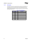
PMDR:
The Power Management Driver Register provides an indication in
memory and I/O space that a wake-up interrupt has occurred. The
PMDR is described in further detail in Section 8.1.11, “Power
Management Driver Register” on page 60.
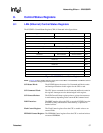
General Control:
The General Control register allows the 82559ER to enter the deep
power-down state and provides the ability to disable the Clockrun
functionality. The General Control register is described in further
detail in Section 8.1.12, “General Control Register” on page 61.
General Status:
The General Status register describes the status of the 82559ER’s
duplex mode, speed, and link. The General Status register is
detailed in Section 8.1.13, “General Status Register” on page 61.
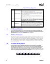
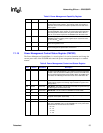
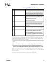
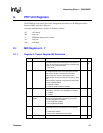
8.1.1 System Control Block Status Word
The System Control Block (SCB) Status Word contains status information relating to the
82559ER’s Command and Receive units.
Bits Name Description
15 CX
Command Unit (CU) Executed.
The CX bit indicates that the CU has
completed executing a command with its interrupt bit set.
14 FR
Frame Received.
The FR bit indicates that the Receive Unit (RU) has
finished receiving a frame.
13 CNA
CU Not Active.
The CNA bit is set when the CU is no longer active and in
either an idle or suspended state.
12 RNR
Receive Not Ready.
The RNR bit is set when the RU is not in the ready
state. This may be caused by an RU Abort command, a no resources
situation, or set suspend bit due to a filled Receive Frame Descriptor.
11 MDI
Management Data Interrupt.
The MDI bit is set when a Management Data
Interface read or write cycle has completed. The management data interrupt
is enabled through the interrupt enable bit (bit 29 in the Management Data
Interface Control register in the CSR).
10 SWI
Software Interrupt.
The SWI bit is set when software generates an
interrupt.
9ER
Early Receive.
The ER bit is used for early receive interrupts.
8FCP
Flow Control Pause.
The FCP bit is used as the flow control pause bit.
7:6 CUS
Command Unit Status.
The CUS field contains the status of the Command
Unit.
5:2 RUS
Receive Unit Status.
The RUS field contains the status of the Receive Unit.
1:0 Reserved These bits are reserved and should be set to 00b.


