


Datasheet
27
Networkin
g
Silicon — GD82559ER
•
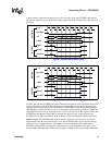
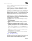
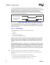
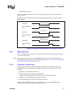
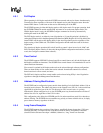
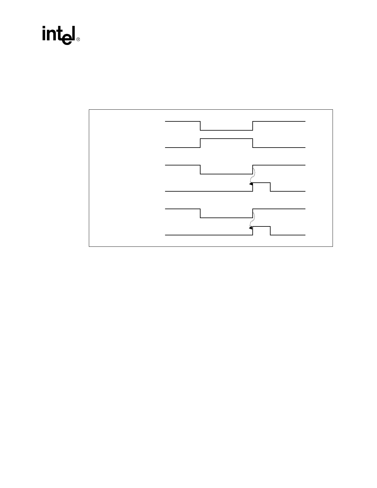
ISOLATE# trailing edge
The internal initialization signal resets the PCI Configuration Space, MAC configuration, and
memory structure.
The behavior of the PCI RST# signal and the internal 82559ER initialization signal are shown in
the figure below.
4.2.5 Wake-u
p
Events
There are two types of wake-up events: “Interesting” Packets and Link Status Change. These two
events are detailed below.
Note:
The wake-up event is supported only if the PME Enable bit in the Power Management Control/
Status (PMCSR) register is set. (The PMCSR is described in Section 7.1.19, “Power Management
Control/Status Register (PMCSR)” on page 55.)
4.2.5.1 “Interestin
g
” Packet Events
In the power-down state, the 82559ER is capable of recognizing “interesting” packets. The
82559ER supports pre-defined and programmable packets that can be defined as any of the
following:
•
ARP Packets (with Multiple IP addresses)
•
Direct Packets (with or without type qualification)
•
Neighbor Discovery Multicast Address Packet (‘ARP’ in IPv6 environment)
•
NetBIOS over TCP/IP (NBT) Query Packet (under IPv4)
•
Internetwork Package Exchange* (IPX) Diagnostic Packet
This allows the 82559ER to handle various packet types. In general, the 82559ER supports
programmable filtering of any packet in the first 128 bytes.
Fi
g
ure 10. 82559ER Initialization u
p
on PCI RST# and ISOLATE#
PCI RST#
Internal hardware
reset
PCI RST#
Internal hardware
reset
ISOLATE#
Internal hardware
reset
D0 - D2 power state
D3 power state
Internal reset
due to ISOLATE#
640 ns
640 ns