


Datasheet
3
Networkin
g
Silicon — GD82559ER
2. GD82559ER Architectural Overview
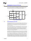
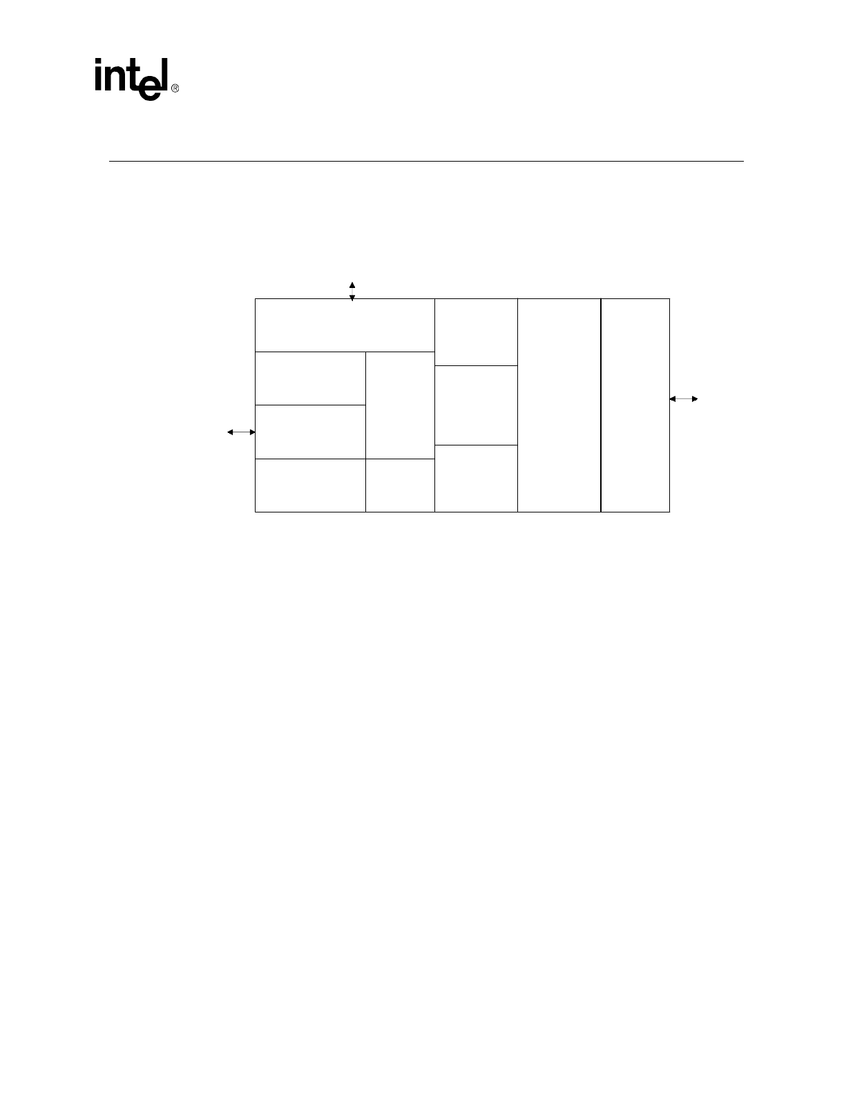
Figure 1 is a high level block diagram of the 82559ER. It is divided into four main subsystems: a
parallel subsystem, a FIFO subsystem, the 10/100 Mbps Carrier-Sense Multiple Access with
Collision Detect (CSMA/CD) unit, and the 10/100 Mbps physical layer (PHY) unit.
2.1 Parallel Subs
y
stem Overview
The parallel subsystem is broken down into several functional blocks: a PCI bus master interface, a
micromachine processing unit and its corresponding microcode ROM, and a PCI Target Control/
Flash/EEPROM interface. The parallel subsystem also interfaces to the FIFO subsystem, passing
data (such as transmit, receive, and configuration data) and command and status parameters
between these two blocks.
The PCI bus master interface provides a complete glueless interface to a PCI bus and is compliant
with the PCI Bus Specification, Revision 2.2. The 82559ER provides 32 bits of addressing and
data, as well as the complete control interface to operate on a PCI bus. As a PCI target, it follows
the PCI configuration format which allows all accesses to the 82559ER to be automatically
mapped into free memory and I/O space upon initialization of a PCI system. For processing of
transmit and receive frames, the 82559ER operates as a master on the PCI bus, initiating zero wait
state transfers for accessing these data parameters.
The 82559ER Control/Status Register Block is part of the PCI target element. The Control/Status
Register block consists of the following 82559ER internal control registers: System Control Block
(SCB), PORT, Flash Control, EEPROM Control, and Management Data Interface (MDI) Control.
The micromachine is an embedded processing unit contained in the 82559ER. The micromachine
accesses the 82559ER microcode ROM working its way through the opcodes (or instructions)
contained in the ROM to perform its functions. Parameters accessed from memory such as pointers
to data buffers are also used by the micromachine during the processing of transmit or receive
frames by the 82559ER. A typical micromachine function is to transfer a data buffer pointer field
to the 82559ER DMA unit for direct access to the data buffer. The micromachine is divided into
two units, Receive Unit and Command Unit which includes transmit functions. These two units
Fi
g
ure 1. 82559ER Block Dia
g
ram
10/100 Mb
p
s
CSMA/CD
Data Interface Unit
(
DIU
)
100BASE-TX/
10BASE-T
PHY
Four Channel
Addressin
g
Unit -
DMA
PCI Bus
Interface Unit
(
BIU
)
PCI Tar
g
et and
Flash/EEPROM
Interface
Micro-
machine
Dual
Ported
FIFO
3 Kb
y
te
Rx FIFO
FIFO Control
3 Kb
y
te
Tx FIFO
Local Memory
Interface
PCI
Interface
TPE
Interface