


IntelP®P Server Board S3420GP TPS Appendix C: POST Code Diagnostic LED Decoder
Appendix C: POST Code Diagnostic LED Decoder
During the system boot process, the BIOS executes a number of platform configuration
processes, each of which is assigned a specific hex POST code number. As each configuration
routine is started, the BIOS displays the POST code to the POST Code Diagnostic LEDs on the
back edge of the server board. To assist in troubleshooting a system hang during the POST
process, you can use the diagnostic LEDs to identify the last POST process executed.
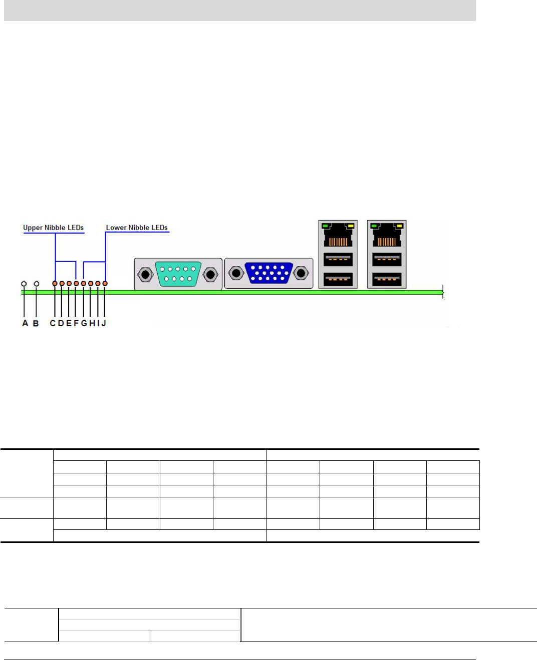
Each POST code is represented by the eight amber diagnostic LEDs. The POST codes are
divided into two nibbles: an upper nibble and a lower nibble. The upper nibble bits are
represented by diagnostic LEDs #4, #5, #6, and #7. The lower nibble bits are represented by
diagnostics LEDs #0, #1, #2, and #3. If the bit is set in the upper and lower nibbles, then the
corresponding LED is lit. If the bit is clear, then the corresponding LED is off.
The diagnostic LED #7 is labeled as “MSB”, and the diagnostic LED #0 is labeled as “LSB”.
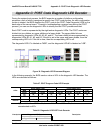
Figure 39. Diagnostic LED Placement Diagram
In the following example, the BIOS sends a value of ACh to the diagnostic LED decoder. The
LEDs are decoded as follows:
Table 67. POST Progress Code LED Example
Upper Nibble LEDs Lower Nibble LEDs
MSB LSB
LED #7 LED #6 LED #5 LED #4 LED #3 LED #2 LED #1 LED #0
LEDs
8h 4h 2h 1h 8h 4h 2h 1h
Status
ON
OFF ON OFF ON OFF ON OFF
1 0 1 0 1 1 0 0
Results
Ah Ch
Upper nibble bits = 1010b = Ah; Lower nibble bits = 1100b = Ch; the two are
concatenated as ACh.
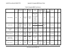
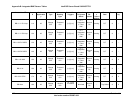
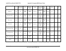
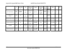
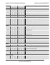
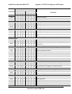
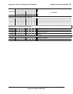
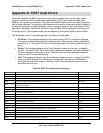
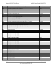
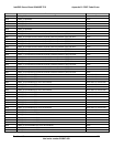
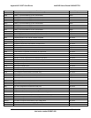
Table 68. Diagnostic LED POST Code Decoder
Diagnostic LED Decoder
O = On, X=Off
Checkpoint
Upper Nibble Lower Nibble
Description
Revision 1.0
Intel order number E65697-003
109