


IntelP®P Server Board S3420GP TPS Connector/Header Locations and Pin-outs
6. Connector / Header Locations and Pin-outs
6.1
The fol
jumper
corresp
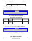
. Board Connector Matrix
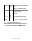
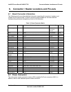
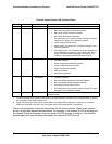
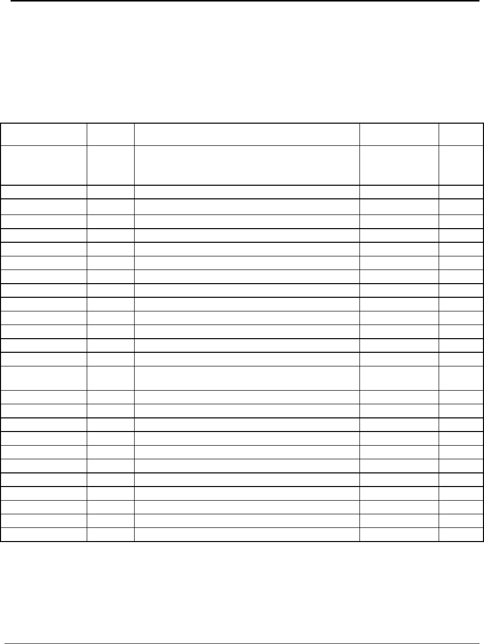
Board Connector Information
lowing section provides detailed information regarding all connectors, headers, and
s on the server board. It lists all connector types available on the board and the
onding reference designators printed on the silkscreen.
Table 31
Connector Quantity Reference Designators Connector Type Pin
Count
Power supply 3 J9A1, J9C1, J9J1 Main power 24
CPU power
P/S aux
8
5
CPU 1 J6G1 CPU sockets 1156
Main memory 6 J8J3, J8J2, J8J1, J9J3, J9J2, J8J4 DIMM sockets 240
Intel
®
RMM3 1 J2C1 Header 34
SAS Mod 1 J2H1 ule Header ?
CPU Fan 1 J6E1 Header 4
System Fans 4 J1J4, J6J2, J7J1, J6B1 Header 4
Battery 1 BT5C1 Battery holder 3
NIC/Stack 2x Dual USB 8 USB 2 J5A1, J6A1
Video 1 J7A1 External DSub 15
Serial port A 1 J8A1 Connector 9
Serial port B 1 J1B2 Header 9
Front panel 1 J4H3 Header 24
USB floopy 1 J1C1 Header 4
Dual- USB Internal
Header
2 J1D1, J1E1 Header 10
PCI-E x16 1 J4B3 Card Edge 164
PCI-E x8 3 J2B2, J3B1, J4B2 Card Edge 98
PCI-E x4 1 J2B1 Card Edge 64
PCI 32 1 J1B1 Card Edge 120
XDP Connector 1 J5J1 Connector 60
Chassis Intrusion 1 J1J1 Header 2
Serial ATA 6 J1H4, J1H1, J1G1, J1H3, J1G3, J1F4 Header 7
IPMB 1 J1H2 Header 4
HSBP 1 J1J1 Header 4
Z-U130 USB 1 J3F2 Header 10
SATA_SGPIO 1 J1J3 Header 4
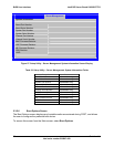
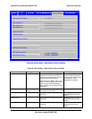
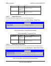
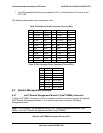
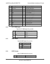
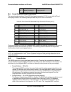
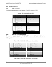
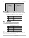
6.2 Power Connectors
The main power supply connection uses an SSI-compliant 2x12 pin connector (J9A1). In
addition, there is one additional power related connector:
Revision 1.0
Intel order number E65697-003
65