


Connector/Header Locations and Pin-outs IntelP®P Server Board S3420GP TPS
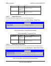
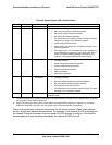
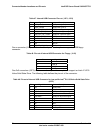
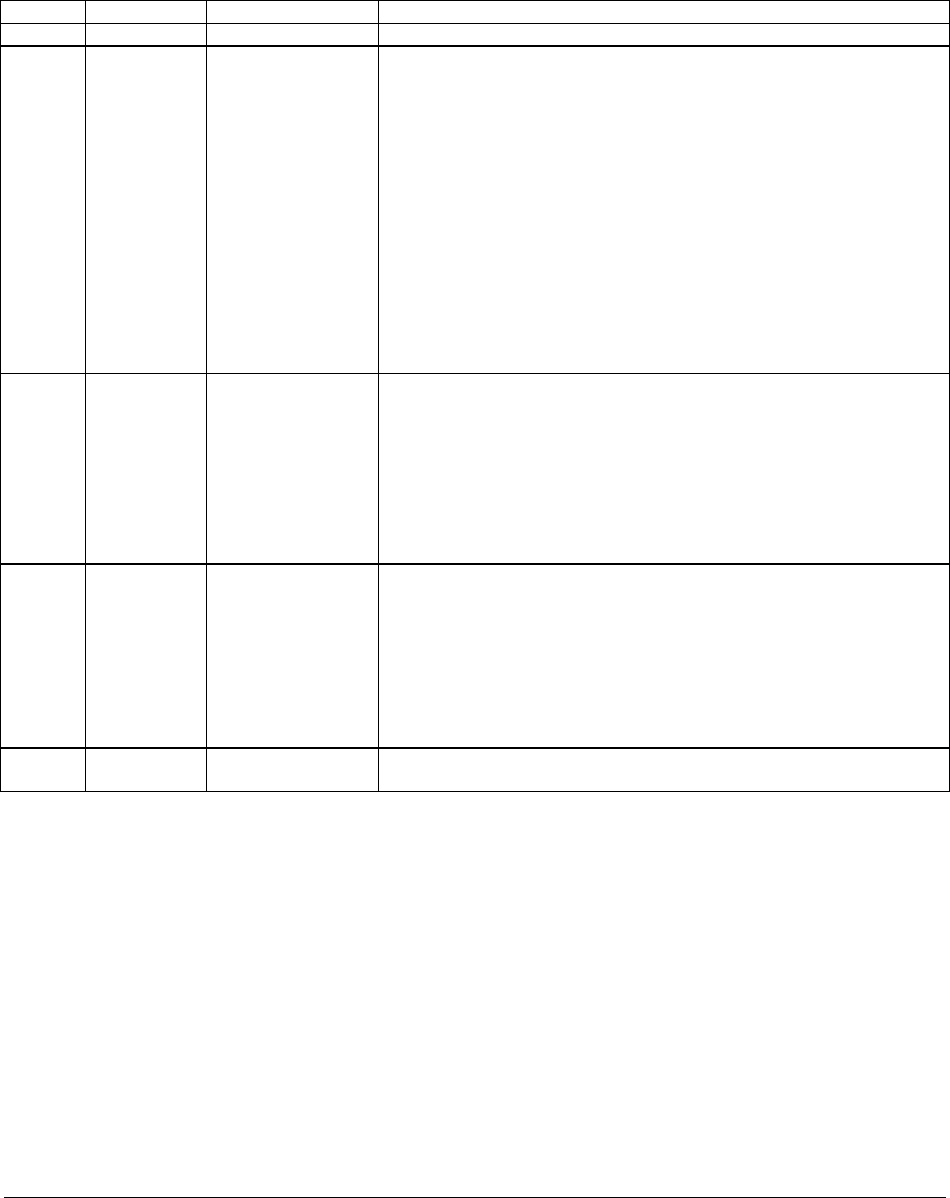
Table 39. System Status LED Indicator States
Color State Criticality Description
Green Solid on Ok System booted and ready
Green ~1 Hz blink Degraded System degra
on d asserted.
on erted.
on ed.
an ystem cooling maintained.
his ndant systems.
Pow r supply predictive failure.
Pow redundancy lost. This does not apply to non-
redundant systems.
ser no
longer has spared DIMMs indicating a redundancy lost
condition. Corresponding DIMM LED should light up.
1
ded:
N -critical temperature threshol
N -critical voltage threshold ass
N -critical fan threshold assert
F
T
redundancy lost, sufficient s
does not apply to non-redu
e
er supply
Correctable errors over a threshold of 10 and migrating to a
spare DIMM (memory sparing). This indicates the u
Amber ~1 Hz blink Non-critical Non-fatal alarm – system is likely to fail:
CATERR asserted.
Critical temperature threshold asserted.
Critical voltage threshold asserted.
Critical fan threshold asserted.
VRD hot asserted.
SM t asserted. I Timeou
Amber Solid on Critical, non-
recoverable
Fatal alarm – system has failed or shutdown:
Thermtrip asserted.
Non-recoverable temperature threshold asserted.
Non-recoverable voltage threshold asserted.
undancy lost, insufficient system cooling. This does
not apply to non-redundant systems.
Power fault / Power Control Failure.
Fan red
Off N/A Not ready AC power off, if no degraded, non-critical, critical, or non-recoverable
conditions exist.
Notes:
1. The BIOS detects these conditions and sends a Set Faul tegrated BMC to provide
the contribution to the stem
2. Support for upper non-critical limit is not provided in the default SDR configuration. However, if a user does
enable this threshold in the SDR, then the system status ibed.
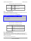
There is no precedence or lock-out mechanism for the control sources. When a new request
arrives, all previous requests are terminated. For example, if the chassis ID LED is blinking and
the chassis ID button is pressed, then the chassis ID LED changes to solid on. If the button is
pressed again with no intervening commands, the chassis ID LED turns off.
t Indication command to the In
sy status LED.
LED should behave as descr
Revision 1.0
Intel order number E65697-003
70