BIOS User Interface IntelP®P Server Board S3420GP TPS
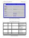
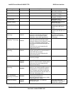
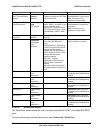
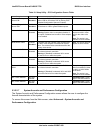
Setup Item Comments
Current Memo
ory
ry
Information only. Displays the speed the mem
Speed
is running at.
DIMM_ XY MM socket present on the board.
Each DIMM socket field reflects one of the following possible
his
ed in
a
the BIOS to optimize memory configuration.
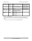
Failed: The DDR3 DIMM installed in this slot is fau
malfunctioning.
Spare Unit: The DDR3 DIMM is functioning as a s
memory RAS purposes.
Note: X denotes the Channel Identifier and Y deno
Identifier within the Channel.
Displays the state of each DI
states:
Installed: There is a DDR3 DIMM installed in t slot.
Not Installed: There is no DDR3 DIMM install
Disabled: The DDR3 DIMM installed in this slot w
this slot.
s disabled by
lty /
pare unit for
te the DIMM
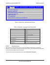
5.3.2.2.3 Mass Storage Controller Screen
he Mass Storage screen allows the user to configure the SATA/SAS controller when it is
present on the baseboard, midplane, or backplane of an Intel system.
T
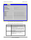
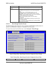
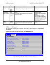
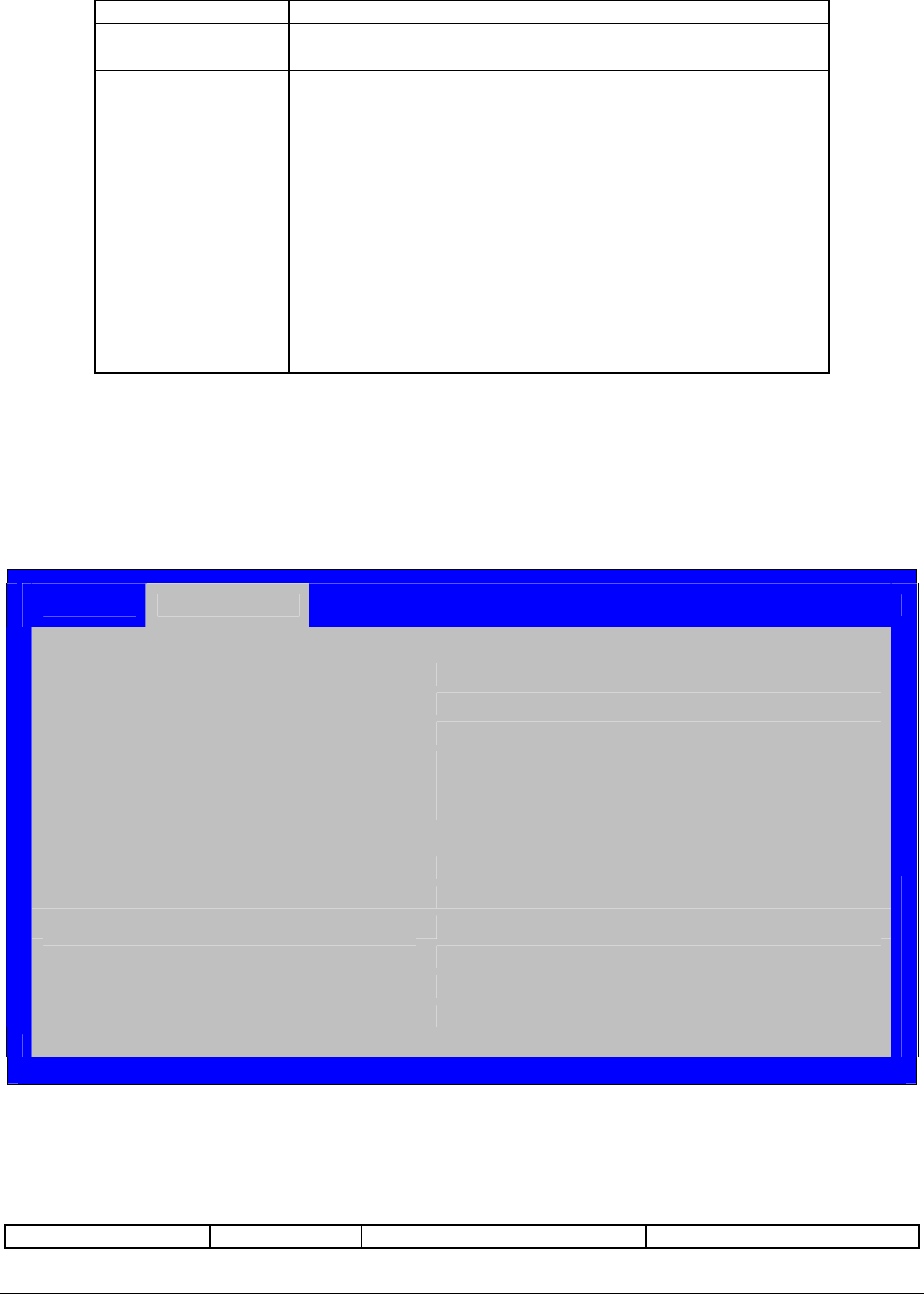
To access this screen from the Main menu, select Advanced > Mass Storage.
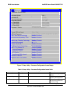
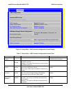
Advanced
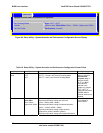
Mass Storage Controller Configuration
Intel
®
Entry SAS RAID Module Enabled / Disabled
Configure Intel
®
Entry SAS RAID Module LSI
®
Integrated RAID / Intel
®
ESRTII
Onboard SATA Controller Enabled / Disabled
ENHANCED / COMPATIBILITY / AHCI / SW
Configure SATA Mode RAID
► SATA Port 0 Not Installed/<Drive Info.>
► SATA Port 1 Not Installed/<Drive Info.>
► SATA Port 2 Not Installed/<Drive Info.>
► SATA Port 3 Not Installed/<Drive Info.>
► SATA Port 4 Not Installed/<Drive Info.>
► SATA Port 5 Not Installed/<Drive Info.>
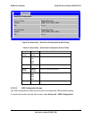
Figure 19. Setup Utility – Mass Storage Controller Configuration Screen Display
Table 15. Setup Utility – Mass Storage Controller Configuration Screen Fields
Setup Item Options Help Text Comments
Revision 1.0
Intel order number E65697-003
46


