


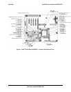
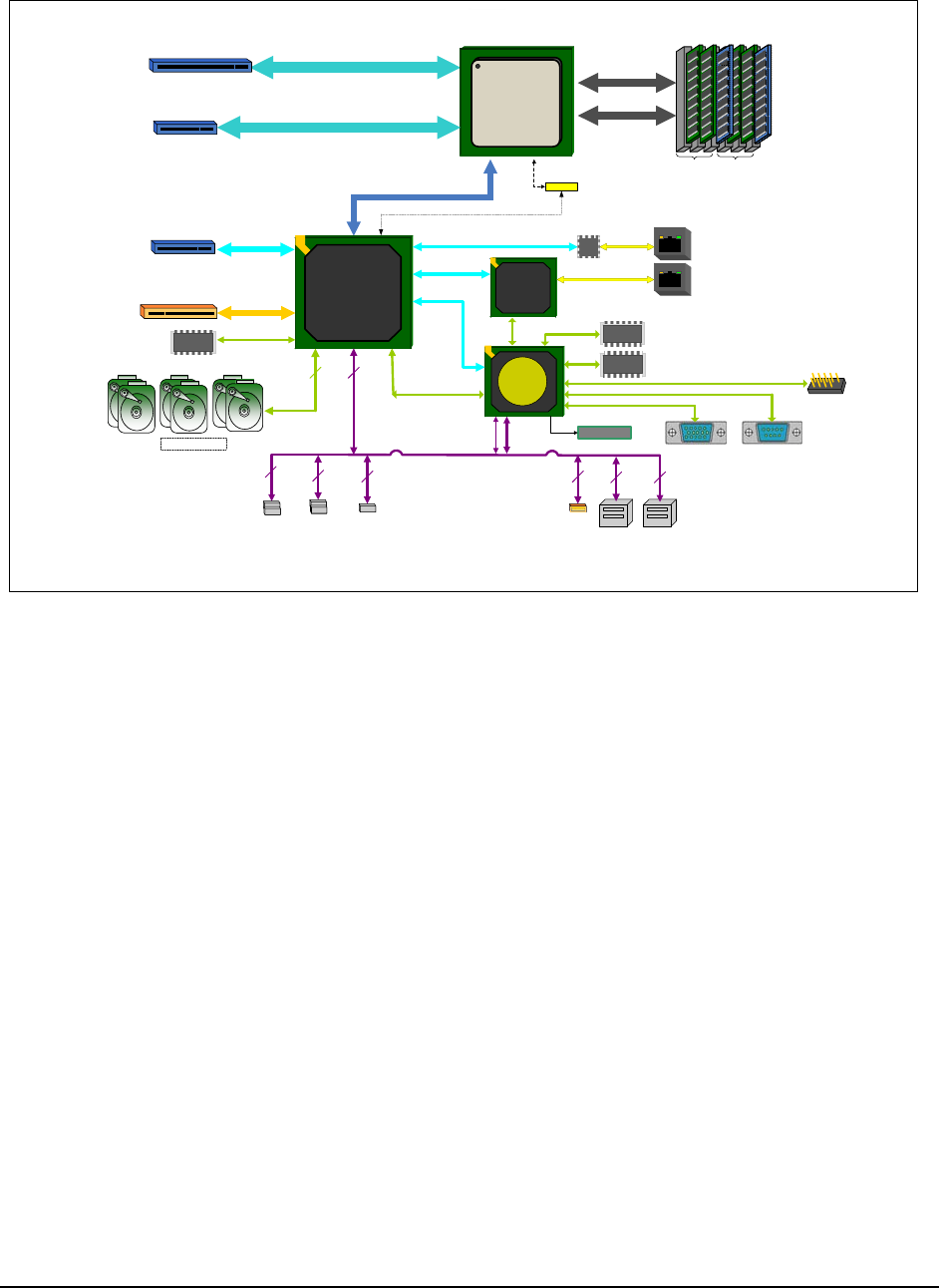
Functional Architecture IntelP®P Server Board S3420GP TPS
612
FLASHFLASH
LPC
SERIAL 1
SATA-II
PCI32
6 onboard
9.6"
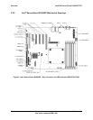
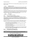
S3420GPLC Block Diagram
ATX - 12" x
Not
1. Video integrated into BMC.
es:
PORT 80
RMII
VIDEO
SATA
FLASHFLASH
BMC Boot SPI
Flash
Intel
®
3420
Chipset
Intel
®
3420
Chipset
Zoar
IBMC
82574
Ch A Ch B
DDR3 (Ch B)
PCIe Gen2 x8
XDP0
x4 DMI Gen1
Slot 5
Slot 1
x4
x1
SPI
USB
Slot 6
Slot 3
( PCIe Gen1 x1 )
PCIe
Gen1
4 unbuffered
or
6 registered
DIMMs
ejd
GbE
GbE
Intel Xeon
® ®
3400
Processor
USB
1.1
USB
2.0
DDR3 (Ch A)
PCIe
PCIe
Gen1
Gen1
x1
82578DM
GbE
PHY
FLASH
DDR2
RMII
(x16 ectoconn r)
PCIe Gen2 x8connec r)
PCI
SERIAL 2
SPI
(FP
headers)
2
(User Bay
headers)
1
2
USB
2
USB
2
Z-U130
1
USB
Floppy
Header
(x8 to
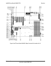
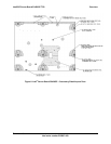
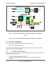
ntel Server Board S3420GP Functional Block Diagram From S3420GPLC
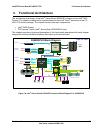
3.1
The t
®
Xeon
The Intel
®
X rocessors processors are made up of multi-core processors
based
3.1.1
The Intel
®
Nehale
FC-
Up to 95 W Thermal Design Power (TDP); processors with higher TDP are not
supported.
(x8 connector)
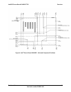
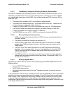
Figure 11. I
®
<TBD>
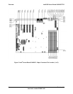
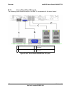
Figure 12. Intel Server Board S3420GP Functional Block Diagram From S3420GPV
®
Processor Sub-System
In el
®
Server Board S3420GP supports the following processor:
Intel
®
3400 Processor series
eon
®
3400 Series p
on the 45 nm process technology.
Intel
®
Xeon
®
3400 Processor
®
Xeon 3400 Series processors highly integrated solution variant is composed of four
m-based processor cores.
LGA 1156 socket package with 2.5 GT/s.
Revision 1.0
Intel order number E65697-003
14