


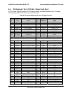
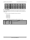
IntelP®P Server Board S3420GP TPS Connector/Header Locations and Pin-outs
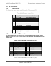
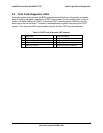
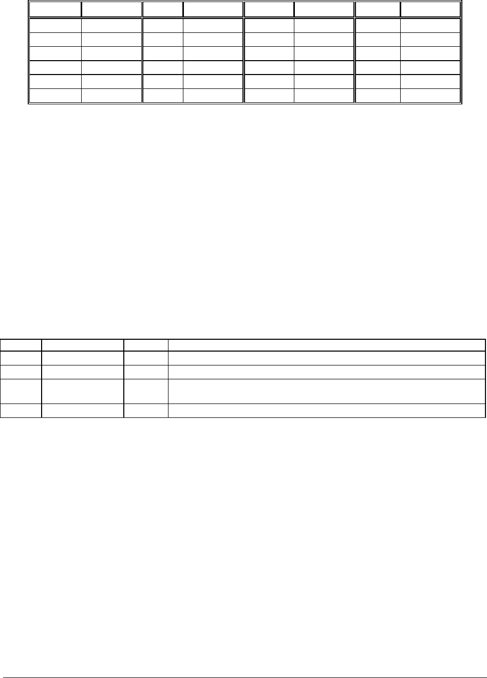
Pin # Signal Pin # Signal Pin # Signal Pin # Signal
B26 C/BE[3]# A26 IDSEL B57 Ground A57 AD[02]
B27 AD[23] A27 +3.3V B58 AD[01] A58 AD[00]
B28 Ground A28 AD[22] B59 V_IO A59 V_IO
B29 AD[21] A29 AD[20] B60 ACK64# A60 REQ64#
B30 AD[19] A30 Ground B61 +5V A61 +5V
B31 +3.3V A31 AD[18] B62 +5V A62 +5V
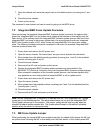
6.7 Fan Headers
The server board provides five SSI-compliant 4-pin fan headers to be used as the CPU and
chassis. The pin configuration for each of the 4-pin fan headers is identical and defined in the
following table.
One 4-pin fan headers are designated as processor cooling fans:
- CPU fan (J6D1)
- SYS1 fan (J1J4)
- SYS2 fan (J6J2)
- SYS3 fan (J7J1)
- SYS4 fan (J6B1)
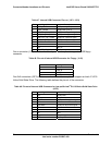
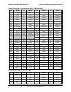
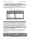
Table 51. SSI 4-pin Fan Header Pin-out (J6E1, J1J4, J6J2, J7J1, J6B1)
Pin Signal Name Type Description
1 Ground GND Ground is the power supply ground
2 12 V Power Power supply 12 V
3 Fan Tach In FAN_TACH signal is connected to the Integrated BMC to monitor the fan
speed
4 Fan PWM Out FAN_PWM signal to control fan speed
Revision 1.0
Intel order number E65697-003
79