


CHAPTER 8
MX Series Router in an ATM Ethernet
Interworking Function
•
MX Series Router ATM Ethernet Interworking Function on page 77
•
Example: Configuring MX Series Router ATM Ethernet Interworking on page 79
MX Series Router ATM Ethernet Interworking Function
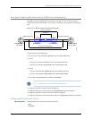
You can configure an MX Series router as part of an ATM Ethernet interworking function
(IWF) scenario mapping outer and inner VLAN tags to ATM Virtual Path Identifier (VPI)
and Virtual Channel Identifier (/VCI).
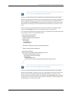
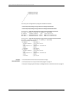
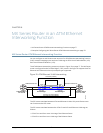
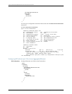
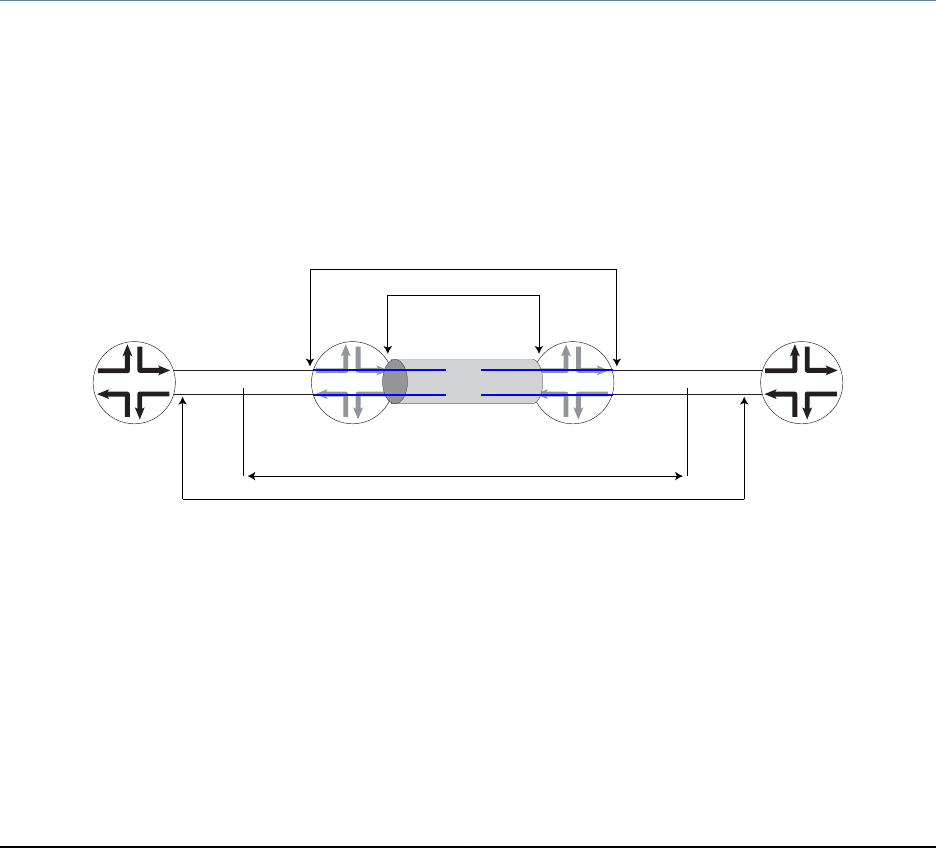
The ATM Ethernet interworking scenario is shown in Figure 10 on page 77. The MX Series
router is configured as the Provider Edge 2 (PE2) router in the figure to support the ATM
Ethernet IWF. Ethernet is the only transport type supported.
Figure 10: ATM Ethernet VLAN Interworking
CE1 CE2
g017428
ATM DSLAM Service Stacked VLAN Service
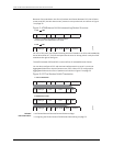
VPI maps to outer VLAN tag
VCI maps to inner VLAN tag
L2 circuits (if-switch)
I/P backhaul
Provider Edge 1 Provider Edge 2
LSP1
LSP2
Customer Edge 1:
ATM DSLAM
Customer Edge 2:
Ethernet B-RAS
PE1 PE2
The PE1 router translates between ATM and Ethernet VLANs. Only an M Series router
can function as the PE1 router.
The PE1 router translates between the ATM VPI and VCI and Ethernet VLAN tags as
follows:
•
ATM VPI to and from outer VLAN tag of the Ethernet frame
•
ATM VCI to and from inner VLAN tag of the Ethernet frame
77Copyright © 2010, Juniper Networks, Inc.