


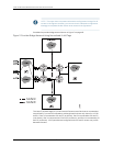
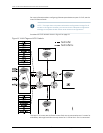
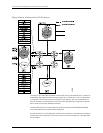

The VLANs’ bridging paths are shown with distinct dashed and dotted lines. The VLANs
at each site are:
•
L2-PE1 at Site 1: VLAN 100 and VLAN 300
•
L2-PE2 at Site 2: VLAN 100
•
L2-PE3 at Site 3: VLAN 100
•
L2-PE4 at Site 4: VLAN 300
NOTE: The configurations in this chapter are only partial examples of
complete and functional router configurations. Do not copy these
configurations and use them directly on an actual system.
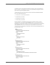
The following is the configuration of interfaces, virtual switches, and bridge domains for
MX Series router L2-PE1:
[edit]
interfaces ge-1/0/0 {
encapsulation flexible-ethernet-services;
flexible-vlan-tagging;
unit 1 {
encapsulation vlan-bridge;
vlan-id 100;
}
unit 11 {
encapsulation vlan-bridge;
vlan-id 301;
}
}
interface ge-2/0/0 {
encapsulation flexible-ethernet-services;
flexible-vlan-tagging;
unit 1 {
encapsulation vlan-bridge;
vlan-id 100;
}
}
interface ge-3/0/0 {
encapsulation flexible-ethernet-services;
flexible-vlan-tagging;
unit 1 {
encapsulation vlan-bridge;
vlan-id 200; # NOTE: 200 is translated to normalized VLAN vlaue
}
}
interfaces ge-4/0/0 {
encapsulation flexible-ethernet-services;
flexible-vlan-tagging;
unit 1 {
encapsulation vlan-bridge;
vlan-tags outer 500 inner 100; # This places two VLAN tags on the provider
# pseudowire
49Copyright © 2010, Juniper Networks, Inc.
Chapter 4: VLANs Within Bridge Domain and VPLS Environments