


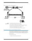

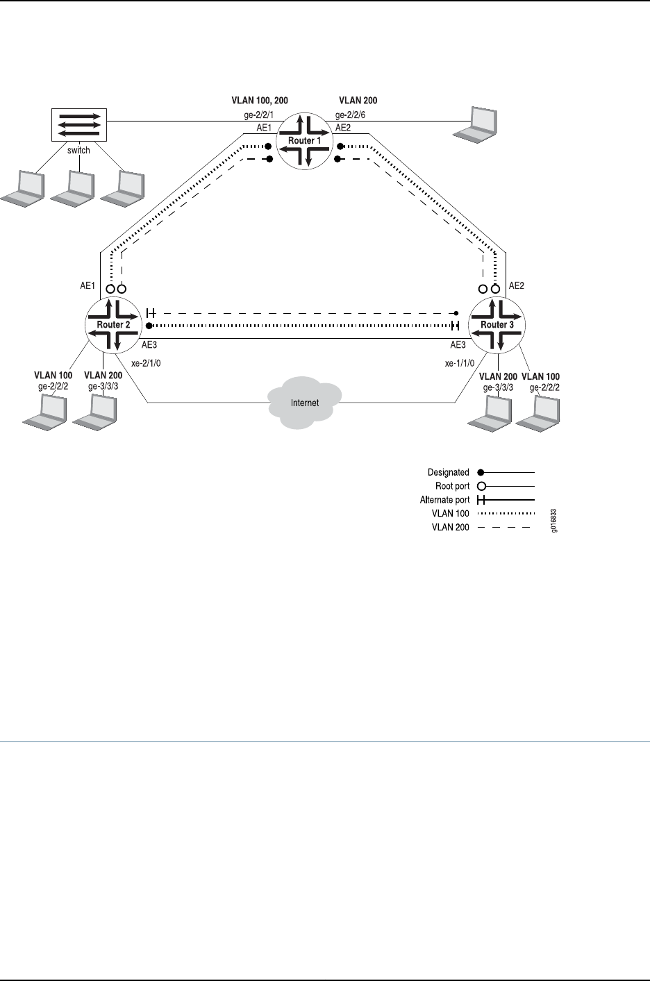
Figure 6: Designated, Root, and Alternate Ports
Related
Documentation
MX Series Ethernet Services Routers Solutions Page•
• Layer 2 Features for a Bridging Environment on page 21
• Example Roadmap: Configuring a Basic Bridge Domain Environment on page 22
• Example Step: Configuring Interfaces and VLAN Tags on page 24
• Example Step: Configuring Bridge Domains on page 30
• Example Step: Configuring Integrated Bridging and Routing on page 34
Example Step: Configuring Integrated Bridging and Routing
Router 2 and Router 3 on the bridging network act as a kind of gateway to the Layer 3
routers in the rest of the network. Router 2 and Router 3 must be able to route packets
aswellasbridgeframes.Thisrequires theconfigurationof integratedroutingand bridging
(IRB) on Routers 2 and 3. The link to the router network is xe-2/1/0 on Router 2 and
xe-1/1/0 on Router 3.
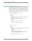
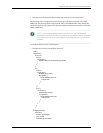
You configure IRB in two steps:
1. Configure the IRB interface using the irb statement.
Copyright © 2010, Juniper Networks, Inc.34
Junos 10.4 MX Series Ethernet Services Routers Solutions Guide