


pdu-threshold 5;
}
}
}
}
}
2.
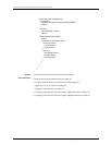
Configure LFM on the PE2 router with CCC:
[edit]
interfaces ge-1/0/0 {
encapsulation ethernet-ccc;
unit 0;
}
protocols {
oam {
ethernet {
link-fault-management {
interface ge-1/0/0 {
pdu-interval 1000;
pdu-threshold 5;
}
}
}
}
}
Related
Documentation
MX Series Ethernet Services Routers Solutions Page•
• Ethernet OAM Link Fault Management on page 137
• Example: Configuring Ethernet LFM Between PE and CE on page 138
• Example: Configuring Ethernet LFM for Aggregated Ethernet on page 140
• Example: Configuring Ethernet LFM with Loopback Support on page 142
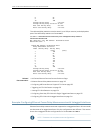
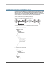
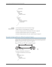
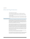
Example: Configuring Ethernet LFM for Aggregated Ethernet
In this example, LFM is configured on an aggregated Ethernet interface (AE0) between
Router 1 and Router 2. When configured on aggregated Ethernet, LFM runs on all the
individual member links. LFM is enabled or disabled on the member links as they are
added or deleted from the aggregation group. The status of individual links is used to
determine the status of the aggregated interface.
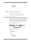
The use of LFM with aggregated Ethernet is shown in Figure 21 on page 140.
Figure 21: Ethernet LFM for Aggregated Ethernet
Copyright © 2010, Juniper Networks, Inc.140
Junos 10.4 MX Series Ethernet Services Routers Solutions Guide