


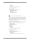
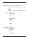
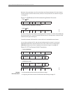
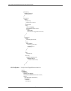
Because of the translation, the flow of packets and frames between PE1 (the M Series
router) and PE2 (the MX series router) routers is not symmetrical, as is shown in Figure
11 on page 78.
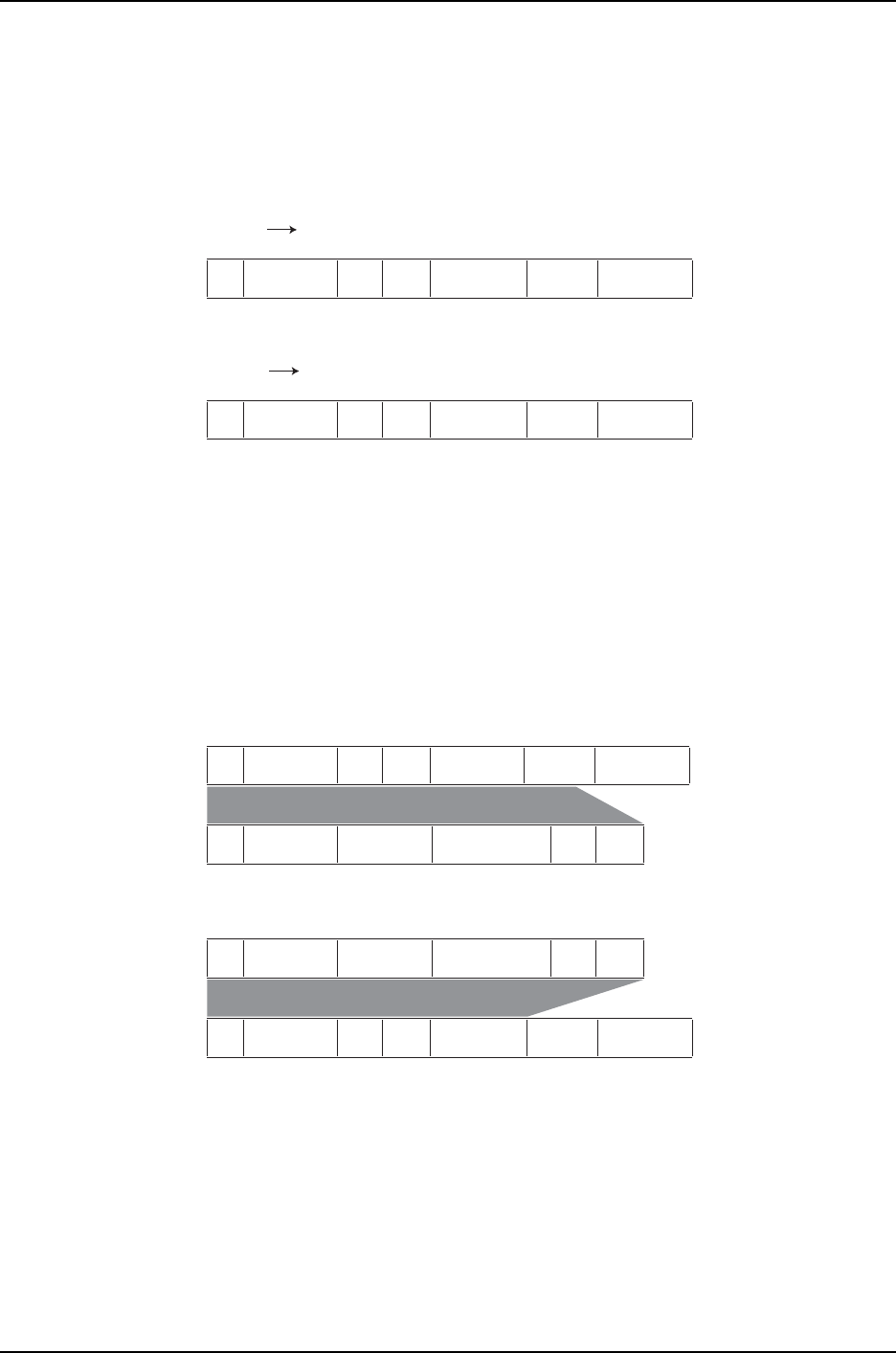
Figure 11: ATM Ethernet VLAN Interworking Packet Structure
g017429
MPLSInner VLANL3 Ethertype SA DA Ethernet
MPLSInner VLANL3 Ethertype SA DA Ethernet
1. PE1 PE2
2. PE2 PE1
“8 bytes” is an ATM cookie added by an M Series ATM pic.
The first 2 bytes of this ATM cookie is inner VLAN.
For PE1 to PE2 traffic, the 8 bytes following the MPLS header is an ATM cookie added by
the M Series ATM PIC. The first two bytes are the inner VLAN tag, which is why the field
extends to the right of the figure.
The traffic between PE2 and CE2 is a normal flow of stacked Ethernet frames.
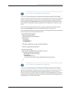
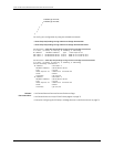
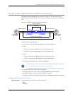
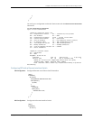
You can also configure a CCC with remote interface switch or Layer 2 circuit over
Aggregated Ethernet on the MX Series router (PE2). When CCC is configured for
Aggregated Ethernet, the flow of packets is as shown in Figure 12 on page 78.
Figure 12: CCC to Stacked VLAN Translation
g017430
L3 Ethertype SA DA MPLSInner VLAN Ethernet
MPLSInner VLANL3 Ethertype SA DA Ethernet
1. CCC to stacked-vlan
2. Stacked-vlan to CCC
L3 Ethertype SA DAIvlan Ovlan
L3 Ethertype SA DAIvlan Ovlan
Related
Documentation
MX Series Ethernet Services Routers Solutions Page•
• Configuring MX Series Router ATM Ethernet Interworking on page 79
Copyright © 2010, Juniper Networks, Inc.78
Junos 10.4 MX Series Ethernet Services Routers Solutions Guide