


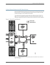

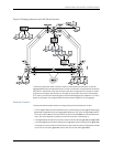
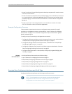
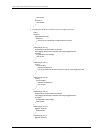
Figure 5: Bridging Network with MX Series Routers
The three routers each have a series of hosts on their Ethernet interfaces, as well as
aggregatedEthernet linksbetween them.Router 2 andRouter 3are linkedto theInternet,
and Router 1 and Router 3 are also linked to switches configured with a range of VLANs,
as shown in the figure. Because the VLAN tags are important, the routers run Multiple
STP (MSTP) onthe linksconnectingthem toprevent bridging loops (RapidSTP, or RSTP,
does not recognize VLAN tags and blocks ports without regard for VLAN tagging).
Example Scenario
The network administrator wants to configure these links and devices so that:
•
Thesix Gigabit EthernetlinksbetweenRouter 1and theother routers(ge-2/1/0through
ge-2/1/5) are gathered into two aggregated Ethernet (AE) links mixing bridged traffic
from the VLANs. AE1 will consist of the first three links and AE2 will use the last three
links. The same approach is taken for the links on Router 2 and Router 3.
•
TheGigabitEthernet links fromRouter 1tothe customerdevices(ge-2/2/1andge-2/2/6
) willbe bridged and include VLANtag100 onge-2/2/1 and VLAN tag200 on ge-2/2/6.
The other two routers, Router 2 and Router 3, also have two ports configured to handle
VLAN 100 on one port (ge-2/2/2) and VLAN 200 on the other (ge-3/3/3).
23Copyright © 2010, Juniper Networks, Inc.
Chapter 2: Basic Layer 2 Features on MX Series Routers