


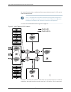


The following happens on the C2 VLAN as a result of the vlan-id none configuration:
•
A MAC table is created for each instance of vlan-id none. All MAC addresses learned
over the interfacesbelongingto thisVPLSinstanceare addedto thistable. The received
or configured VLAN tags are not considered when the MAC addresses are added to
this table. This is a case of shared VLAN learning.
•
Packets with a single VLAN tag value of 301 are accepted on interface ge-1/0/0.11. The
VLAN tag value 301 is then popped and removed from the frame of this packet.
•
Packets with a single VLAN tag value of 302 are accepted on interface ge-6/0/0.11.
The VLAN tag value 302 is then popped and removed from the frame of this packet.
•
All packets sent on pseudowires will not have any VLAN tags used to identify the
incoming Layer 2 logical interface.
NOTE: The packet can still contain other customer VLAN tags.
•
Packets received from pseudowires are looked up in the MAC table associated with
the VPLS instance. Any customer VLAN tags in the frame are ignored.
Related
Documentation
MX Series Ethernet Services Routers Solutions Page•
• VLANs Within a Bridge Domain or VPLS Instance on page 43
• Packet Flow Through a Bridged Network with Normalized VLANs on page 44
• Configuring a Normalized VLAN for Translation or Tagging on page 45
Example: Configuring One VPLS Instance for Several VLANs
This topic provides a configuration example to help you effectively configure a network
of Juniper Networks MX Series Ethernet Services Routers for a bridge domain or virtual
privateLAN service(VPLS)environment.Theemphasishereis onchoosingthe normalized
virtual LAN (VLAN) configuration. The VPLS configuration is not covered in this chapter.
For more information about configuring Ethernet pseudowires as part of VPLS, see the
Junos OS Feature Guide.
NOTE: This topic does not present exhaustive configuration listings for all
routers in the figures. However, you can use it with a broader configuration
strategy to complete the MX Series router network configurations.
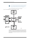
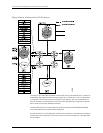
Consider the VPLS network shown in Figure 9 on page 56.
55Copyright © 2010, Juniper Networks, Inc.
Chapter 4: VLANs Within Bridge Domain and VPLS Environments