


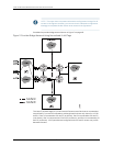
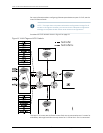
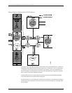

to P0 and P1, Site 2 is connected to P0 and P2 (not shown), Site 3 is connected to P2
and P3, and Site 4 is connected to P1 and P3. VPLS pseudowires configured on the PE
and P routers carry traffic between the sites.
The pseudowires for the VPLS instances are shown with distinct dashed and dotted
lines. The VLANs at each site are:
•
L2-PE1 at Site 1: VLAN 100 and VLAN 300
•
L2-PE2 at Site 2: VLAN 100
•
L2-PE3 at Site 3: VLAN 100
•
L2-PE4 at Site 4: VLAN 300
Service provider SP-1 is providing VPLS services for customer C1 and C2. L2-PE1 is
configured with a VPLS instance called customer-c1-vsi. The VPLS instance sets up
pseudowires to remote Site 2 and Site 3. L2-PE1 is also configured with a VPLS instance
called customer-c2-vsi. The VPLS instance sets up a pseudowire to remote Site 4.
The following is the configuration of interfaces, virtual switches, and bridge domains for
MX Series router L2-PE1:
[edit]
interfaces ge-1/0/0 {
encapsulation flexible-ethernet-services;
flexible-vlan-tagging;
unit 1 {
encapsulation vlan-vpls;
vlan-id 100;
}
unit 11 {
encapsulation vlan-vpls;
vlan-id 301;
}
}
interfaces ge-2/0/0 {
encapsulation flexible-ethernet-services;
flexible-vlan-tagging;
unit 1 {
encapsulation vlan-vpls;
vlan-id 100;
}
}
interfaces ge-3/0/0 {
encapsulation flexible-ethernet-services;
flexible-vlan-tagging;
unit 1 {
encapsulation vlan-vpls;
vlan-id 200; # Should be translated to normalized VLAN value
}
}
interfaces ge-6/0/0 {
encapsulation flexible-ethernet-services;
flexible-vlan-tagging;
unit 11 {
53Copyright © 2010, Juniper Networks, Inc.
Chapter 4: VLANs Within Bridge Domain and VPLS Environments