


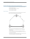
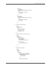
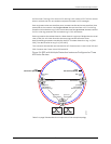
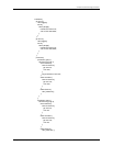
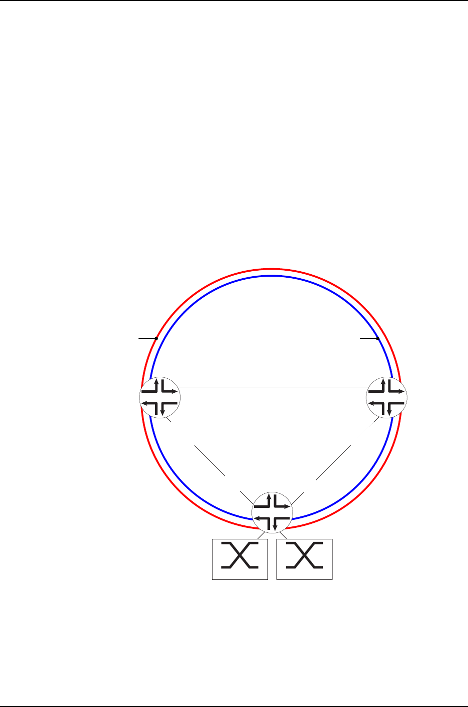
an RPL owner. The ring-1 RPL owner is CS1; the ring-2 RPL owner is CS2. The RPL owners
block or unblock the RPL as conditions require and initiate R-APS messages.
Each ring instance has two interface ports (an east interface and a west interface) that
participate in the instance. Interface ge-2/0/8.0, the west interface on CS2, is the ring
protection linkend wherering-2’sRPL terminates.Interfacege-3/2/4.0,the east interface
on CS1, is the ring protection link end where ring-1’s RPL terminates.
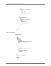
Each ring instance has a data channel. A data channel is a group of bridge domain virtual
LAN (VLAN) IDs. All VLAN IDs within the same ring interface share the same
data-forwarding properties controlled by the ERP. The data channel on ring-1 is [200,
300]. The data channel on ring-2 is [500, 600].
Two customer site switches are connected to AS1. Customer site 1 uses VLANs 200 and
300. Customer site 2 uses VLANs 500 and 600.
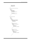
Figure 24: ERP with Multiple Protection Instances Configured on Three
MX Series Routers
AS1
CS1 CS2
g017469
ge-5/2/3.0
west-interface
ge-2/0/4.0
east-interface
ring-1
data-channel [200,300]
ring-2
data-channel [500,600]
RPL owner
ring-1
ge-3/2/4.0
east-interface
RP link end ring-1
ge-2/0/8.0
west-interface
RP link end ring-2
ge-2/0/5.0
west-interface
ge-2/1/1.0
east-interface
RPL owner
ring-2
Customer Site 2
VLANs [500,600]
Customer Site 1
VLANs [200,300]
Table 5 on page 156 describes the components of the example topology.
155Copyright © 2010, Juniper Networks, Inc.
Chapter 13: Ethernet Ring Protection