


Example Step: Configuring Spanning Tree Protocols
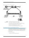
Configure the Spanning Tree Protocol on all three routers. This is necessary to avoid the
potential bridging loop formed by the triangular architecture of the routers. MSTP is
configured on the three routers so the set of VLANs has an independent, loop-free
topology. The Layer 2 traffic can be load-shared over 65 independent paths (64 Multiple
Spanning Tree Instances [MSTIs] and one Common and Internal Spanning Tree [CIST]),
eachspanninga setof VLANs.Theconfigurationnames, revision level,and VLAN-to-MSTI
mapping mustmatch in order to utilizethe load-sharingcapabilitiesof MSTP(otherwise,
each router will be in a different region).
To configure the Spanning Tree Protocol on all three routers:
1.
Configure MSTP on Router 1:
[edit]
protocols {
mstp {
configuration-name mstp-for-R1-2-3; # The names must match to be in the same
region
revision-level 3; # The revision levels must match
bridge-priority 0; # This bridge acts as root bridge for VLAN 100 and 200
interface ae1;
interface ae2;
msti 1 {
vlan100; # This VLAN corresponds to MSTP instance 1
}
msti 2 {
vlan200; # This VLAN corresponds to MSTP instance 2
}
}
}
2.
Configure MSTP on Router 2:
[edit]
protocols {
mstp {
configuration-name mstp-for-R1-2-3; # The names must match to be in the same
region
revision-level 3; # The revision levels must match
interface ae1;
interface ae3;
msti 1 {
vlan100; # This VLAN corresponds to MSTP instance 1
bridge-priority 4096; # This bridge acts as VLAN 100 designated bridge on
# the R2-R3 segment
}
msti 2 {
vlan200; # This VLAN corresponds to MSTP instance 2
}
}
}
Copyright © 2010, Juniper Networks, Inc.32
Junos 10.4 MX Series Ethernet Services Routers Solutions Guide