


Example: Configuring Ethernet Ring Protection for MX Series Routers
This example configures Ethernet ring protection for three MX Series router nodes:
•
Example Topology on page 148
•
Router 1 (RPL Owner) Configuration on page 149
•
Router 2 Configuration on page 150
•
Router 3 Configuration on page 152
Example Topology
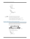
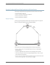
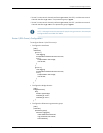
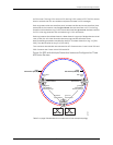
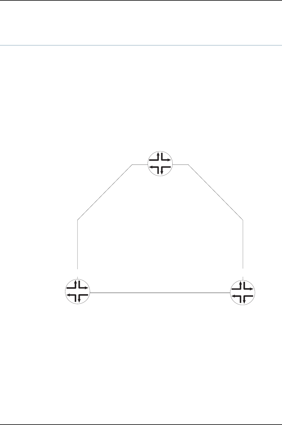
The links connecting the three MX Series routers are shown in Figure 23 on page 148.
Figure 23: Ethernet Ring Protection Example Nodes
RPL Owner
R-APS
Channel
ge-1/2/4 ge-1/0/1
ge-1/0/3 ge-1/0/2
East
East East
West
pg101
pg102
pg103
3
2
1
g016988
ge-1/0/4 ge-1/2/1
West West
This example uses the following topology details for Ethernet ring protection:
•
Router 1 is the RPL owner. The node identification for Router 1 is MAC address
00:01:01:00:00:01.
•
The RPL link is ge-1/0/1.1 (this is also the R-APS messaging control channel).
•
Traffic flows among the nodes in the configured bridge domains. (That is, only the
control channels are configured.)
•
Router 1’s east control channel interface is ge-1/0/1.1 (the RPL) and the west control
channel interface is ge-1/2/4.1. The protection group is pg101.
Copyright © 2010, Juniper Networks, Inc.148
Junos 10.4 MX Series Ethernet Services Routers Solutions Guide