


Example: Configuring MX Series Router ATM Ethernet Interworking
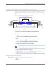
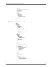
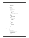
Consider the router topology shown in Figure 13 on page 79. The MX Series router is
configured as the Provider Edge 2 (PE2) router in the figure to support the ATM Ethernet
IWF.
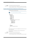
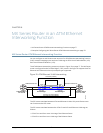
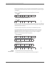
Figure 13: ATM Ethernet VLAN Interworking
CE1 CE2
g017428
ATM DSLAM Service Stacked VLAN Service
VPI maps to outer VLAN tag
VCI maps to inner VLAN tag
L2 circuits (if-switch)
I/P backhaul
Provider Edge 1 Provider Edge 2
LSP1
LSP2
Customer Edge 1:
ATM DSLAM
Customer Edge 2:
Ethernet B-RAS
PE1 PE2
The relevant router interfaces are:
•
On CE1, the CE1–PE1 interface is at-2/0/0 with IP address 30.1.1.1/24
•
On PE1:
•
The PE1–CE1 interface is at-2/0/1 with no IP address required
•
The PE1–PE2 interface is ge-5/0/0 with IP address 20.1.1.1/24
•
On PE2:
•
The PE2–CE2 interface is ge-0/2/0 with no IP address required
•
The PE2–PE1 interface is ge-0/2/8 with IP address 20.1.1.10/24
•
CE2 interface is ge-0/0/0 with IP address 30.1.1.10/24
NOTE: These are not complete router configurations.
•
Configuring PE2 with a Layer 2 Circuit on page 79
•
Configuring PE2 with a Layer 2 Circuit over Aggregated Ethernet on page 82
•
Configuring PE2 with a Remote Interface Switch on page 85
•
Configuring PE2 with a Remote Interface Switch over Aggregated Ethernet on page 88
Configuring PE2 with a Layer 2 Circuit
CE1 Configuation Configure Ethernet over ATM on the ATM interface
[edit]
interfaces {
79Copyright © 2010, Juniper Networks, Inc.
Chapter 8: MX Series Router in an ATM Ethernet Interworking Function