


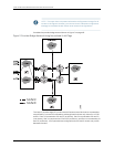
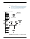
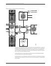

Bridge domain c1–vlan-100 for customer-c1–virtual-switch has five logical interfaces:
•
Logical interface ge-1/0/0.1 configured on physical port ge-1/0/0.
•
Logical interface ge-2/0/0.1 configured on physical port ge-2/0/0.
•
Logical interface ge-3/0/0.1 configured on physical port ge-3/0/0.
•
Logical interface ge-4/0/0.1 can exist on an extended port/subinterface defined by
the pair ge-4/0/0 and outer-vlan-tag 500.
•
Logical interface ge-5/0/0.1 can exist on an extended port/subinterface defined by
the pair ge-5/0/0 and outer-vlan-tag 500.
The association of the received packet to a logical interface is done by matching the
VLAN tags of the received packet with the VLAN tags configured on one of the logical
interfaces on that physical port. The vlan-id 100 configuration within the bridge domain
c1–vlan-100 sets the normalized VLAN value to 100.
The following happens as a result of this configuration:
•
Packets received on logical interfaces ge-1/0/0.1 or ge-2/0/0.1 with a single VLAN tag
of 100 in the frame are accepted.
•
Packets received on logical interface ge-3/0/0.1 with a single VLAN tag of 200 in the
frame are accepted and have their tag values translated to the normalized VLAN tag
value of 100.
•
Packets received on logical interfaces ge-4/0/0.1 and ge-5/0/0.1 with outer tag values
of 500 and inner tag values of 100 are accepted.
•
Unknownsource MAC addressesand unknown destination MAC addresses arelearned
based on their normalized VLAN values of 100 or 300.
•
All packets sent on a logical interface always have their associated vlan-id value(s) in
their VLAN tag fields.
Configuration and function of bridgedomain c2-vlan-300 for customer-c2-virtual-switch
is similar to, but not identical to, that of bridge domain c1-vlan-100 for
customer-c1-virtual-switch.
Related
Documentation
MX Series Ethernet Services Routers Solutions Page•
• VLANs Within a Bridge Domain or VPLS Instance on page 43
• Packet Flow Through a Bridged Network with Normalized VLANs on page 44
• Configuring a Normalized VLAN for Translation or Tagging on page 45
Example: Configuring a Provider VPLS Network with Normalized VLAN Tags
This topic provides a configuration example to help you effectively configure a network
of Juniper Networks MX Series Ethernet Services Routers for a bridge domain or virtual
privateLAN service(VPLS)environment.Theemphasishereis onchoosingthe normalized
virtual LAN (VLAN) configuration. The VPLS configuration is not covered in this chapter.
51Copyright © 2010, Juniper Networks, Inc.
Chapter 4: VLANs Within Bridge Domain and VPLS Environments