


M160 Internet Router Hardware Guide
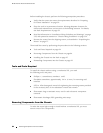
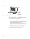
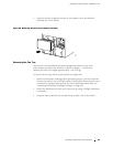
Figure 33: Removing an SFM
1931
Locking tab
Ejector handle
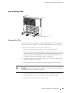
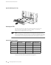
Removing the MCSs
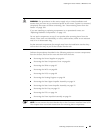
The router can have an MCS in each o f the slots labeled MCS 0 and MCS 1 at the rear
of the chassis, as shown in Figure 3. Each MCS weighs a pproximately 2.5 lb (1 kg).
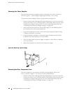
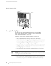
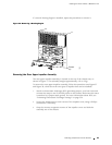
To remove the MCSs, follow this procedure (see Figure 34):
1. Place an electrostatic bag or antistatic mat on a flat, stable surface.
2. A tt ach an electrostatic discharge (ESD) grounding strap to your bare wrist and
connect the strap to one of the ESD p oints on the chassis. Make sure the router
is attached to a pr oper earth ground. F or more information about ESD, see
“Preventing Electrostatic Discharge Damage” on page 226.
3. Push the end of each extractor clip (located at each end of the MCS) outward.
4. Grasp the extractor clips and slide the MCS about h alfway out of the chassis .
5. Place one hand under the MCS to support it, slide it completely out of the
chassis, and place it on the antistatic mat or in the electrostatic bag.
If a second MCS is installed, repeat the procedure to remove it.
88 Rem oving Components from the Chassis