


Replacing Hardware Components
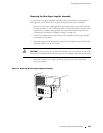
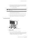
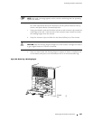
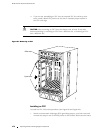
Figure 84: Insert the PC Card
1925
PCG 0
SFM 0
SFM 1
MCS 0
RE 0
Replacing a Rout ing Engine
The Routing Engines are hot-pluggable, as described in Field-Replaceable Units
(FRUs) on page 4. For a description of the effect of removing a Routing Engine,
seeHostModuleonpage22.ToreplaceaRoutingEngine,performthefollowing
procedures:
Removing a Routing Engine on page 165
Installing a Routing Engine on page 168
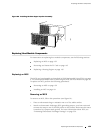
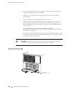
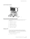
Removing a Routing Engine
To remove a Routing Engine, follow this procedure (see Figure 85):
1. Place an electrostatic bag or antistatic mat on a flat, stable surface.
2. A tt ach an electrostatic discharge (ESD) grounding strap to your bare wrist and
connect the strap to one of the ESD p oints on the chassis. Make sure the router
is attached to a pr oper earth ground. F or more information about ESD, see
“Preventing Electrostatic Discharge Damage” on page 226.
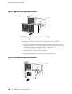
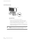
3. Remove the rear component cover by loosening the thumbscrew at each
corner of the cover and pulling it straight off the chassis . For complete
instructions, see “Removing the Rear Component Cover” on page 86.
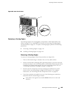
4. If two host modules are installed, use one of the following two methods to
determine which is functioning as master:
Note which of the green host module MASTER LEDs is lit on the craft
interface.
Replacing Host Module Com ponents 165