


M160 Internet Router Hardware Guide
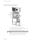
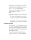
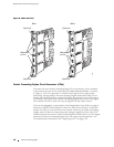
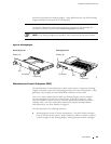
Figure 6: FPC1 and FPC2
1187
Ejector lever
FPC 2
Ejector lever
Offline buttons
(on PICs)
Ejector lever
FPC 1
Ejector lever
Offline buttons
(on FPC)
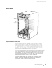
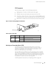
Packet Forwarding Engine Clock Generators (PCGs)
The router has two Packet Forwarding Engine Clock Generators (PCGs) installed
in the slots at the rear of the chassis that are labeled
PCG 0 and PCG 1,asshown
in Figure 3. The PCGs generate a 125-MHz clock signal used to gate packet
processing. During startup, the active Routing Engine determines which PCG is
master and which is backup, and the MCS relays the decision to the PCGs and to
themodulesandASICsinthePacketForwardingEnginethatusetheclocksignal.
The modules and ASICs then use only the signal from the master source.
PCGs are hot-pluggable, as described in Field-Replaceable Units (FRUs) on page 4.
Removal or failure of the backup PCG does not affect router function. When the
master PCG fails or is removed from the chassis, however, the Packet Fo rwarding
Engine resets so that the components start using the signal from the other PCG
(which becomes the master). Packet forwarding halts while there is no clock signal,
because the Packet Forwarding Engine does not accept incoming packets. For
PCG replacement instructions, see “Replacing a PCG” on page 176.
18 Packet Forwarding Engine