


Maintaining Hardware Com ponents
For further description of the output from the command, see the JUNOS
Internet Software Operational Mode Command Reference: Protocols , Class
of Service, Chassis, and Management.
Maintaining Host Module Components
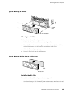
The router can have a Routing Engine in each of the slots labeled RE 0 and RE
1
and a Miscellaneous Control Subsystem (MCS) in each of the slots labeled
MCS 0 and MCS 1 at the rear of the chassis, as shown in Figure 3. Each paired
Routing Engine and MCS function together as a host module. To maintain
the host module, perform the following procedures regularly:
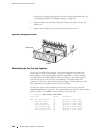
Check the LCD and the host module LEDs on the craft interface. T he LCD
reports host module status during normal operation and describes the cause of
failures when they occur. The green LEDs labeled
ONLINE and MASTER light
steadily for the master host module when it is functioning normally. The
ONLINE LED also lights for the standby host module if it is installed. For more
information about the LEDs and LCD, see Craft Interface on page 27.
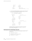
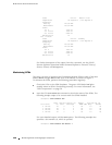
Issue the CLI s how chassis routing-engine command to check the status of the
Routing Engines. As shown in the sample output, the master Routing Engine is
designated
Master in the Current state field:
user@host> show chassis routing-engine
Routing Engine status:
Slot 0:
Current state Master
Election priority Master (default)
Temperature 37 degreesC/98degrees F
DRAM 768 MB
Memory utilization 18 percent
CPU utilization:
User 0 percent
Background 0 percent
Kernel 2 percent
Interrupt 0 percent
Idle 98 percent
Model RE-2.0
Serial ID 8b00000792898b01
Start time 2003-04-29 16:09:49 PDT
Uptime 16 days, 3 hours, 6 minutes, 34 seconds
Load averages: 1 minute 5 minute 15 minute
0.00 0.00 0.00
Routing Engine status:
Slot 1:
Current state Backup
Election priority Backup (default)
Temperature 36 degreesC/96degrees F
DRAM 768 MB
Memory utilization 16 percent
CPU utilization:
User 0 percent
Maintaining Host Module Com ponents
131