


M160 Internet Router Hardware Guide
For more information about the command, see the JUNOS Pr o tocols, Class of
Service, and System Basics Command Reference.
3. Press the power switch for both power supplies to the OFF (0) position. The
switches are on the circuit breaker box.
4. A tt ach an electrostatic discharge (ESD) grounding strap to your bare wrist and
connect the strap to one of the ESD p oints on the chassis. Make sure the router
is attached to a pr oper earth ground. F or more information about ESD, see
“Preventing Electrostatic Discharge Damage” on page 226.
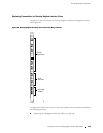
5. Disconnect any external devices connected to the CIP. For instructions, see
“Replacing the Management Ethernet Cable” on page 146, “Replacing the
Console or Auxiliary Cable” on page 146, and “Replace Alarm Relay Wires”
on page 147.
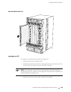
6. Using a Phillips screwdriver, loosen and remove the screw at each end of the
CIP faceplate.
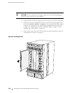
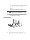
7. Grasp the CIP a nd slide it out of the chassis. Place it in the electrostatic bag or
on the antistatic mat.
CAUTION: Be sure to slide the CIP straight within the slot to avoid damaging the
connector pins on the front of the midplane.
142 R eplacing the CIP and Routing Engine Interface Port Cables