


M160 Internet Router Hardware Guide
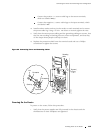
2. For each power supply, verify that the source power cables are connected to
the appropriate terminal on the circuit br eaker box: the positive (+) sour ce
cable to the return terminal (labeled
RTN(+)) and the negative (–) source cable to
the input terminal (labeled
–48V).
3. Verify that an external management device is connected to one of the
RoutingEngineportsontheCIP(
AUXILIARY, CONSOLE,orETHERNET). For more
information on connecting management devices, see Connecting the Router
to Management and Alarm Devices on page 112.
4. Turn on the power to the external management device.
5. Press one power switch on the circuit box to the ON ( | )position.
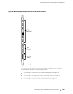
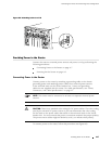
6. Observe the LEDs on the power supply faceplate:
As an enhanced power supply powers on, the green CB ON LED lights
steadily, the blue
OUTPUT OK LED blinks for a short time, then lights
steadily, and the amber
CB OFF LED does not light.
As an original power supply powers on, the green CB ON LED lights
steadily, the blue
OUTPUT OK LED blinks for a short time, then lights
steadily, and the amber
CB OFF and NO AIRFLOW LEDs do not light.
NOTE: After powering off a power supply, wait at least 60 seconds before turning
it back on. After powering on a power supply, wait at least 60 seconds before
turning it off.
If the router is completely powered down when you pow er on the power supply,
the Routing Engine boots as the power supply completes its startup sequence. If
the Routing Engine finishes booting and you need to power down the router
again, first issue the CLI
request system halt command. For more information, see
“Disconnecting Power from the Router” on page 200.
After a power supply is powered on, it can take up to 60 seconds for status
indicators—such as LEDs on the power supply,
show chassis commands, and
messages on the craft interface LCD—to indicate that the power supply is
functioning normally. Ignore error indicators that appear during the first 60 seconds.
7. Press the o ther power switch on the circuit br eaker box to the ON ( | ) position
and observe the LEDs on the second power supply faceplate. They should light
as described in the previous step.
If the LEDs are not lit in the appropriate pattern after 60 seconds, repeat the
power supply and cable installation procedures described in “Reinstalling
thePowerSupplies”onpage109and“ConnectingPowertotheRouter”
on page 117.
8. On the external management device connected to the Routing Engine, monitor
the startup process to verify that the system has booted properly.
120 P roviding Power to the Router