


M160 Internet Router Hardware Guide
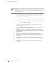
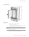
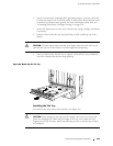
CAUTION: Be sure to slide the CIP straight within the slot to avoid damaging the
connector pins on the front of the midplane.
4. Using a Phillips scre wdriver, tighten the scre w at each end of the C IP faceplate.
5. Reattach an external management device to one of the Routing Engine ports
on the CIP (
AUXILIARY, CONSOLE,orETHERNET). Also reattach alarm relay contacts
if desired. For instructions, see “Replacing the Management Ethernet Cable”
on page 146, “Replacing the Console or Auxiliary Cable” on page 146, and
“Replace Alarm Relay Wires” on page 147.
6. Power on the router and verify correct startup by performing the procedures in
“Powering On the Router” on page 119.
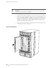
Figure 65: Installing the CIP
1259
R
144 R eplacing the CIP and Routing Engine Interface Port Cables