


Maintaining Hardware Com ponents
The following guidelines apply s pecifically to fiber-optic cable:
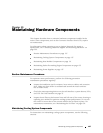
When you unplug a fiber-optic cable from a PIC, always place a rubber safety
plug over the transceiver on the PIC faceplate and on the end of the cable.
Anchor fiber-optic cable to avoid stress on the connectors. When attaching
fiber to a PIC, be sure to secure the fiber so it is not supporting its own weight
as it hangs to the floor. Never let fiber-optic cable hang free from the connector.
Avoid bending fiber-optic cable beyond its bend radius. An arc smaller than
a few inches can damage the cable and cause problems that are difficult to
diagnose.
Frequent plugging and unplugging of fiber-optic cable into a nd out of optical
instruments, such as ATM or SONET/SDH analyzers, can cause damage to
the instruments that is expensive to repair. Instead, attach a short fiber
extension to the optical equipment. Any wear and tear due to frequent
plugging and unplugging is then absorbed by the short fiber extension, which
is easy and inexpensive to replace.
Keep fiber-optic cable connections clean. Small micro-deposits of oil and dust
in the canal of the transceiver or cable connector could cause loss of light,
reducing signal power and possibly causing intermittent problems with the
optical connection.
To clean the transceivers, use an appropriate fiber-cleaning device, such as
RIFOCS Fiber Optic Adaptor Cleaning Wands (part number 946). Follow the
directions for the cleaning kit you use.
After you have cleaned the transceiver on the fiber-optic PIC, make sure that
the connector tip of the fiber-optic cable is clean. Use only an approved
alcohol-free fiber-optic cable cleaning kit, such as the Opptex Cletop-S® Fiber
Cleaner. Follow the directions for the cleaning kit you use.
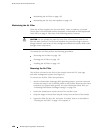
Maintaining the PCGs
The router has two Packet Forwarding Engine Clock Generators (PCGs) installed in
the slots labeled
PCG 0 and PCG 1 on the rear of the chassis, as shown in Figure 3.
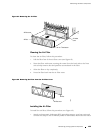
To maintain the PCGs, perform the following procedures regularly:
Check the LEDs on the PCG faceplates. T he green LED labeled OK lights
steadily when the PCG is functioning normally. The blue LED labeled
MASTER lights steadily on the master PCG. For more information, see “PCG
Components” on page 19.
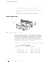
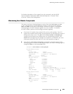
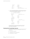
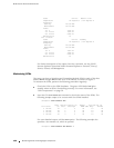
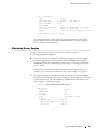
Issue the CLI s how chassis environment pcg command to check the status of
the PCGs. As shown in the sample output, the master PCG is designated
Online - Master clock and the standby PCG Online - Standb y:
user@host> show chassis environment pcg
PCG 0 status:
Maintaining Packet Forwarding Engine Components
135