


Preparing for Router Installation
Chassis Grounding
To meet safety and electromagnetic interference (EMI) requirements and to
ensure proper operation, the r outer must be adequately grounded before power
is connected. A pair of threaded inserts (PEM nuts) are provided on the right
rear of the chassis for connecting the router to earth ground.
CAUTION: Before router installation begins, a licensed electrician must attach a
cable lug to the grounding and power cables that you supply. A cable with an
incorrectly attached lug can damage the router (for example, by causing a short
circuit).
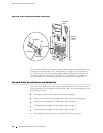
To ground the router, connect a grounding cable to earth ground and then
attach it to the chassis grounding points. The grounding points are spaced at
0.625-in. (15.86-mm) centers. The accessory box shipped with the router
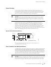
includes the cable lug that attaches to the grounding cable (see Figure 28) and
the UNC 1/4–20 screws (American) used to secure the grounding cable to the
grounding points. (The cable lug shown in Figure 28 is also used for the DC power
cables.) Thegroundingcablemustbeabletohandleupto82A.
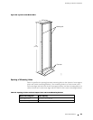
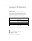
Figure 28: Power and Grounding Cable Lug
Crimp area
All measurements in inches
0.28
2 holes
2.25
0.25 0.37
0.63
g002137
0.55
End view
0.08
Thegroundingcablemustbe8-AWG(8.4m
2
) w ire, minimum, or
as permitted by the local code.
Power, Conn ection , and Cable Specifications
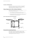
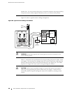
To supply power to the router, connect power cables to a separate, dedicated power
source for each power supply and attach the cables to the terminal studs on the
circuit breaker box. Most sites distribute power through a main conduit that leads
to frame-mounted power distribution panels, one of which might be located at the
top of the rack that houses the router. A pair of cables (one input and one return)
connects each set of terminal studs to the power distribution panel.
CAUTION: There is no standard color coding for DC power cables. The color coding
used by the external DC power source at your site determines the color coding
for the leads on the power cables that attach to t he terminal studs on the circuit
Power Guidelines, Requirements, and Specifications 67