


Hardware Component Overview
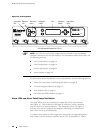
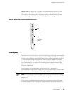
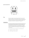
YELLOW ALARM (see Figure 16). A system condition that causes the red or yellow
alarm LED to light on the craft interface also activates the corresponding alarm
relay contact. For instructions for attaching a device to the alarm relay contacts,
see “Connecting to an External Alarm-Reporting Device” on page 115.
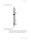
Figure 16: Alarm Relay Contacts and BITS Input Ports
BITS A
BITS B
LINK
RED ALARM
YELLOW
ALARM
LINK
1173
Alarm relay
contacts
BITS
input ports
NC
C
NO
NC
C
NO
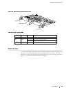
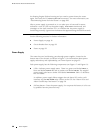
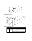
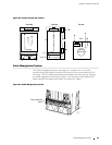
Power System
The router uses DC power. There are two load-sharing, pass-through power supplies
located at the bottom rear of the chassis, as shown in Figure 2. The power supplies
connect to the midplane, which distributes power to router components according
to their individual voltage requirements. When the power supplies are installed
and operational, they automatically share the electrical load. If a power supply
stops functioning for any r eason, the remaining power supplies instantly begin
providing all the power the router needs for normal functioning and can pro vide
full power indefinitely.
Power supplies are hot-removable and hot-insertable, as described in
Field-Replaceable Units (FRUs) on page 4. To avoid electrical injury, carefully follow
the instructions in “Replacing a Power Supply” on page 197.
NOTE: After powering off a power supply, wait at least 60 seconds before turning
it back on. After powering on a power supply, wait at least 60 seconds before
turning it off.
If the router is completely powered down when you pow er on the power supply,
the Routing Engine boots as the power supply completes its startup sequence. If
Power System 35