


Preparing for Router Installation
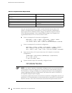
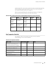
Table 17: DC Power and Grounding Cable Specifications
Cable T ype Quantity and S
pecification
Maximum
Equal Length
Power
Eight 4-AWG(16 mm
2
) wires, minimum, or as permitted
by the local code
None
Grounding One 8-AWG (8.4 mm
2
) wire, minimum, or as permitted
by the local code
None
WARNING: For field-wiring connections, use copper conductors only.
For other electrical safety information, see “Electrical Safety Guidelines and
Warnings” on page 227.
CAUTION: Power cords and cables must not block access to router components or
drape where people could trip on them.
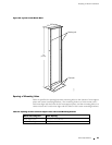
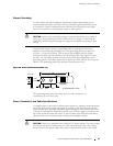
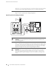
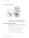
Figure 30 shows how to attach the power cables. The power cables attach
to the 1/4–20 UNC terminal studs located on the circuit breaker box—
the input set of studs is labeled
–48V andthereturnsetislabeledRTN(+).
Thenutsandlockingwashersusedtosecurethepowercablelugson
the terminal studs are preinstalled on the studs.
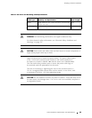
The tool for loosening or tightening the nuts on the terminal studs is a
7/16-in. hexagonal-head external drive socket wrench, or nut driver, with
a minimum of 30 lb-in. (3.5 Nm) tightening torque.
CAUTION: Do not substitute a metric nut driver or wrench. A tool t hat does not fit
thenutsexactlycandamagethem.Ifa7/16-in.toolisnotavailable,usepliersor
an adjustable wrench.
Power Guidelines, Requirements, and Specifications 69