


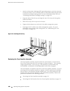


Replacing Hardware Components
Removing the Rear Upper Impeller Assembly
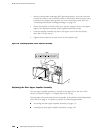
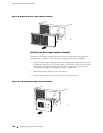
To remove the rear upper impeller assembly, follow this procedure (see Figure 77
and Figure 78, which show the two types of impeller that can be installed):
1. A tt ach an electrostatic discharge (ESD) grounding strap to your bare wrist and
connect the strap to one of the ESD p oints on the chassis. Make sure the router
is attached to a pr oper earth ground. F or more information about ESD, see
“Preventing Electrostatic Discharge Damage” on page 226.
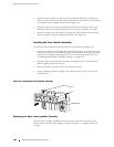
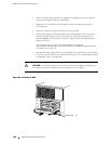
2. Loosen the thumbscrew at each corner of the impeller cover, using a Phillips
screwdriver if necessary.
3. Grasp the thumbscrews at opposite corners of the impeller cover and slide the
assembly halfway out of the chassis.
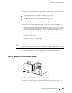
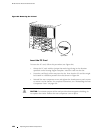
CAUTION: To avoid injury, as you slide the assembly out of the chassis do not touch
any part of the impeller behind the front panel—the impeller might still be spinning.
4. When the impeller is no longer spinning, slide the assembly completely
outofthechassis.
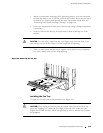
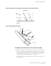
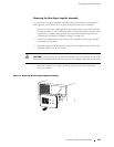
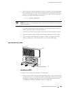
Figure 77: Removing the Rear Upper Impeller Assembly
1211
Replacing Cooling System Components 157