


M160 Internet Router Hardware Guide
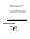
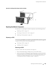
1. A tt ach an electrostatic discharge (ESD) grounding strap to your bare wrist and
connect the strap to one of the ESD p oints on the chassis. Make sure the router
is attached to a pr oper earth ground. F or more information about ESD, see
“Preventing Electrostatic Discharge Damage” on page 226.
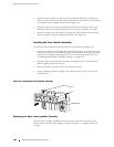
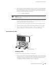
2. Orient the impeller so that the label is on the top. Align the rails on the upper
edges of the impeller assembly with the guides inside the chassis.
3. Pushtheimpellerassemblyupandtotherighttostartitintothechassis,
then slide it all the way in.
4. Tighten the thumbscrew at each corner of the impeller cover.
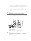
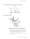
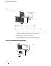
Figure 76: Installing the Rear Lower Impeller Assembly
1915
Rails
Guides
Label
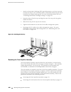
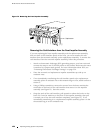
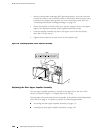
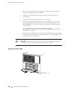
Replacing the Rear Upper Impeller Assembly
The rear upper impeller assembly is located at the upper left of the rear of the
chassis, as shown in Figure 2. It weighs about 4 lb (1.8 kg).
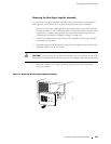
The assembly is hot-removable and hot-insertable, as described in Field-Replaceable
Units (FRUs) on page 4. To replace it, perform the following procedures:
Removing the Rear Upper Impeller Assembly on page 157
Installing the Rear Upper Impeller Assembly on page 158
156 R eplacing Cooling System Components