


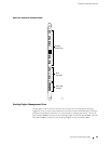

Hardware Component Overview
Relay Contacts” on page 34. The LCD on the craft interface reports the cause
of the alarm, as described in “LCD Alarm Mode” on page 30.
To deactivate red and yellow alarms, press the button labeled
ACO/L T (for “alarm
cutoff/lamp test”), w hich is located to the left of the alarm LEDs. Deactivating an
alarm turns off both LEDs and deactivates the device attached to the corresponding
alarm relay contact on the CIP. However, the LCD continues to report the alarm
message until you clear the condition that caused the alarm.
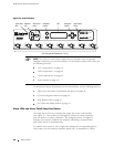
Table 9 describes the alarm LEDs and alarm cutoff button in more detail.
Table 9: Alarm LEDs and Alarm Cutoff/Lamp Test Button
Shape Color State Description
Red On steadily Critical alarm LED—Indicates a critical condition
that can cause the router t o stop functioning.
Possible causes include component r emo val,
failure, or overheating.
Yellow On steadily Warning alarm LED—Indicates a serious but
nonfatal error condition, such as a maintenance
alert or a significant increase in component
temperature.
——
Alarm cutoff/lamp test button—Deactivates red
and yellow alarms. Causes all LEDs on the craft
interface to light (f or testing purposes), when
pressed and held.
LCD and Navigation Buttons
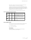
A four-line LCD is located in the craft interface, along with six navigation buttons.
The LCD operates in two modes, as described in the following sections:
LCDIdleModeonpage29
LCD Alarm Mode on page 30
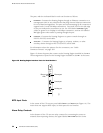
LCD Idle Mode
During normal operation, the LCD operates in idle mode and reports
current status information, as shown in Figure 12.
Craft Interface 29