


M160 Internet Router Hardware Guide
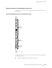
5. Orient the terminal block according to the labels to the left of the appropriate
relay contact (
NC means “normally closed,” C means “common,” and NO
means “normally open”).
6. Plug the terminal block into the relay contact and use a 2.5 mm flat-blade
screwdriver to tighten the screws on the face of the block.
7. Attach the other end of the wires to the external device.
Replacing Cooling System Components
For instructions on replacing cooling system components, see the following sections:
Replacing the Fan Tray on page 148
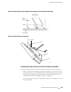
Replacing the Front Impeller Assembly on page 150
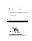
Replacing the Rear Lower Impeller Assembly on page 1 54
Replacing the Re ar Upper Impeller Assembly on page 156
Replacing the Fan Tray
To replace the fan tray, perform the following procedures:
Removing the Fan Tray on page 148
Installing the Fan Tray on page 149
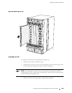
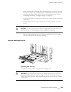
Removing the Fan Tray
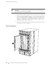
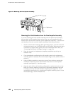
The fan tray is located behind the cable management system on the front of the
chassis, as shown in Figure 1. It weighs approximately 13 lb (5.9 kg).
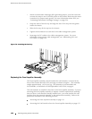
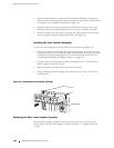
To remove the fan tray, follow this procedure (see Figure 69):
1. Unwrap any PIC cables from the spools on the cable management system
and remo v e the cables from the tra y. Arrange the cables so that they do not
block the front of t he cable management system and tray, and secure them
with temporary fasteners so that they are not supporting their own weight
as they hang from the connector.
CAUTION: Do not let fiber-optic cable hang free from the connector. Do not allow
fastened loops of cable to dangle, which stresses the cable at the fastening point.
148 R eplacing Cooling System Components