


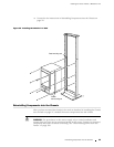

Installing the Router without a Mechanical Lift
1. Place an electrostatic bag or antistatic mat on a flat, stable surface.
2. A tt ach an electrostatic discharge (ESD) grounding strap to your bare wrist and
connect the strap to one of the ESD p oints on the chassis. Make sure the router
is attached to a pr oper earth ground. F or more information about ESD, see
“Preventing Electrostatic Discharge Damage” on page 226.
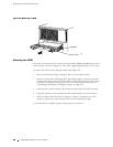
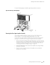
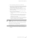
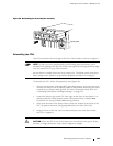
3. Locate the FPC or blank panel located in the leftmost slot of the card cage
on the front of the chassis. It is directly below the offline button on the cr aft
interface that is labeled
FPC0.
4. If the slot is covered by a blank panel, you can leave it in place. If the slot
contains an FPC, perform the following steps:
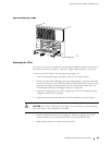
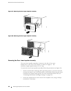
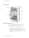
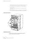
a. LoosenthethumbscrewateachendoftheFPC,usingaPhillipsscrewdriver
if necessary.
b. Pull the ends of the ejector levers, which are adjacent to the thumbscrews,
away from the face of the FPC until they are nearly perpendicular to it.
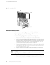
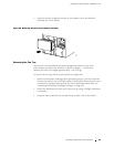
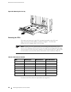
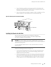
c. Grasp the top and bottom flanges of the card carrier and slide the FPC
about halfway out of the card cage.
d. Place one h and around the front of the FPC (the PIC h ousing) and the other
hand under it to support it. Slide the FPC completely out of the chassis,
and place it on the antistatic mat or in the electrostatic bag.
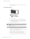
CAUTION: The weight of the FPC is concentrated in the back end. Be pr epared to
accept the full weight—up to 29 lb (13.2 kg)—as you slide the FPC out of the chassis.
When the FPC is out of the chassis, do not hold it by t he ejector levers, bus bars,
or edge connectors. They cannot support its weight.
Do not stack FPCs on top of one another after removal. Place each one individually
in an electrostatic bag or on its own antistatic mat on a flat, stable surface.
5. Repeat Step 4 for each FPC card carrier or blank cover, proceeding from
left to right.
Removing Components from the C hassis 95