


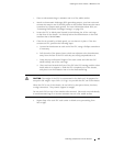

Installing the Router without a Mechanical Lift
If a second Routing Engine is installed, repeat the procedure to remove it.
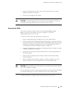
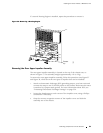
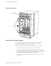
Figure 36: Removing a Routing Engine
PCG 0
SFM 0
SFM 1
MCS 0
RE 0
RE 1
PCG 1
1950
Extractor
clip
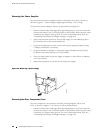
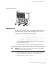
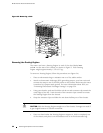
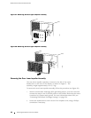
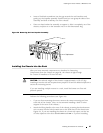
Removing the Rear Upper Impeller Assembly
The rear upper impeller assembly is located at the top of the chassis rear, as
shown in Figure 2. The assembly weighs approximately 4 lb (1.8 kg).
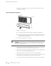
To remove the rear upper impeller assembly, follow this procedure (see Figure 37
and Figure 38, which show the two types of impeller that can be installed):
1. A tt ach an electrostatic discharge (ESD) grounding strap to your bare wrist and
connect the strap to one of the ESD p oints on the chassis. Make sure the router
is attached to a pr oper earth ground. F or more information about ESD, see
“Preventing Electrostatic Discharge Damage” on page 226.
2. Loosen the thumbscrew at each corner of the impeller cover, using a Phillips
screwdriver if necessary.
3. Grasp the screws at opposite corners of the impeller cover and slide the
assembly out of the chassis.
Removing Components from the C hassis 91