


M160 Internet Router Hardware Guide
2. If the PIC uses fiber-optic cable, verify that there is a rubber safety cap over
each transceiver on the f aceplate. Install a cap if necessary.
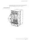
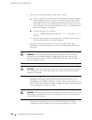
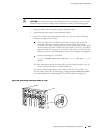
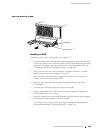
3. Align the notches in the connector at the rear of the PIC with the notches in the
PIC slot in the FPC and then slide the PIC in until it lodges firmly in the FPC.
CAUTION: Slide the PIC straight into the slot to avoid damaging the components on
the bottom of the PIC.
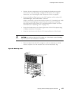
4. Tighten the thumbscrews at the top and bottom of the PIC faceplate
simultaneously and at about the same rate (tightening the two screws
alternately or at very different rates can cause the PIC to become lodged
in the FPC slot, making it difficult to turn the screws). Verify that the PIC
is seated properly.
5. If the PIC uses fiber-optic cable, remove the rubber safety cap from each
transceiver and the end of each cable.
WARNING: Do not look directly into the ends of fiber-optic cables or into the
transceivers on the interface faceplate. Single-mode fiber-optic cable and the
interfaces that use it (such as ATM and SONET/SDH interfaces) emit laser light
that can damage your eyes.
CAUTION: Do not leave a fiber-optic transceiver uncovered except when inserting
or removing cable. The safety cap keeps the port clean and prevents accidental
exposure to laser light.
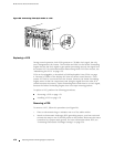
6. Insert the appropriate cables into the cable connectors on the PIC.
7. Arrange each cable in the cable management system to pre vent the cable
from dislodging or developing stress points. Secure the cable so that it is not
supporting its own weight as it hangs to the floor. Place excess cable out of the
way in a neatly coiled loop in the cable management system. Placing fasteners
on the loop helps to maintain its shape.
CAUTION: Do not let fiber-optic cable hang free from the connector. Do not allow
fastened loops of cable to dangle, which stresses the cable at the fastening point.
182 R eplacing Packet Forwarding Engine Components