


Hardware Component Overview
PCG Components
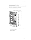
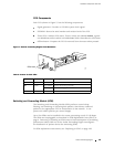
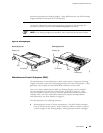
Each PCG (shown in Figure 7) has the following components:
Signal generator—Provides a 125-MHz system clock signal.
EEPROM—Stores the serial number and revision level o f the PCG.
Three LEDs—Indicate PCG status. There is a blue one labeled MASTER, a green
one labeled
OK, and an amber one labeled FAIL. Table 6 describes the LED states.
Offline button—Prepares the PCG for removal from the router when pressed.
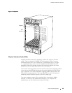
Figure 7: Packet Forwarding Engine Clock Generator
1181
Offline button
LEDs
Table 6: States for PCG LEDs
Label Color State Description
MASTER Blue On steadily
PCG is master.
On steadily PCG is functioning normally.OK
Green
Blinking
PCG is starting up.
FAIL Amber On steadil
y
PCG has fai
led.
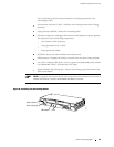
Switching and Forwardin g Module (SFM)
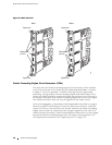
The Switching and Fo rw arding Module (SFM) p erforms route lookup,
filtering, and switching on incoming data packets, then directs outbound
packets to the appropriate FPC for transmission to the network. It can
process 4 0 million packets per second (Mpps).
Up to four SFMs can be installed in the router, processing a total of 160 Mpps.
The SFMs are hot-pluggable, as described in Field-Replaceable Units (FRUs) on
page 4. Removing or inserting an SFM causes a brief interruption in forwarding
performance (about 500 ms) as the Packet Forwarding Engine reconfigures
the distribution of packets across the remaining SFMs.
For SFM replacement instructions, see “Replacing an SFM” on page 188.
Packet Forwarding Engine 19