


M160 Internet Router Hardware Guide
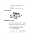
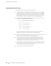
NOTE: The messages in the craft interface LCD and the output from CLI show
commands refer to the power supply on the right as PEM 0 and the power supply
on the left as
PEM 1.
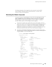
For further description of the output from the command, see the JUNOS
Internet Software Operational Mode Command Reference: Protocols, Class of
Service, Chassis, and Management.
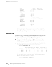
Check the red and yellow alarm LEDs and the LCD on the craft interface.
Power supply failure or removal triggers an alarm that causes one or both of
the LEDs to light and an error message to appear on the LCD. You can display
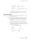
the associated error messages by issuing the following CL I command:
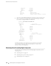
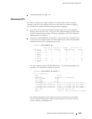
user@host> show chassis alarms
For a list of possible alarm messages, see “Chassis and Interface Alarm
Messages” on page 209.
Verify that the power source has the proper current rating and that each power
supply is connected to a separate power source.
Verify that the cable or cord connecting the power supply to the external
power source is securely in place and that there is no moisture accumulating
near the router.
Verify that the cable or cord from the power source to the router is not
damaged. If the insulation is cracked or broken, replace the cable or cord
immediately.
Verify that the power cables or cord do not touch or obstruct access to other
router components, and that they do not drape where people could trip
on them.
Verify that the air flow in and out of cooling system components is not
obstructed.
138 Maintaining Power Supplies