


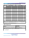
QPC414 Network card 105
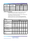
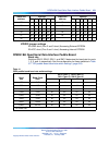
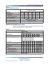
QPC71 E and M/DX Signaling and Paging Trunk cards
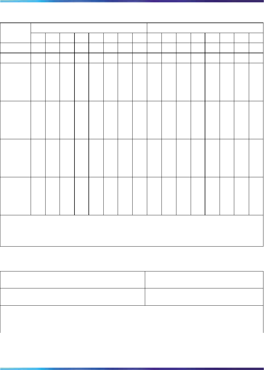
Unit 0 E35 switch Unit 1 E5 switch
Applicati
on
1234
5
6
7
81234
5
6
7
8
E and M off off off
on
off off
on
off off off off
on
off off
on
off
Paging off off off off off off off off off off off off off off off off
DX 2-wir
e (condu
ctor loop
< 2.5 K
3
/4)
on on
off off off
on
off
on on on
off off off
on
off
on
DX 2-wir
e (condu
ctor loop
> 2.5 K
3
/4)
on on on on
off
on
off
on on on on on
off
on
off
on
DX 4-wir
e (condu
ctor loop
< 2.5 K
3
/4)
off off off off
on on
off
on
off off off off
on on
off
on
DX 4-wir
e (condu
ctor loop
> 2.5 K
3
/4)
off off
on on on on
off
on
off off
on on on on
off
on
Note: DX trunks must be balanced correctly. If the loop is <2.5 K
3
/4, far-end balancing is standard.
If the loop is >2.5 K
3
/4, far end balancing requires standard plus 2.5 K
3
/4. To connect PBX to PBX,
switches should be arranged for loops to be >2.5 K
3
/4 at one end and <2.5 K
3
/4 at the other. Apply
similar treatment when connecting to Pulse QPJ69 trunks.
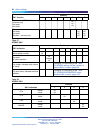
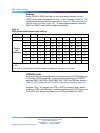
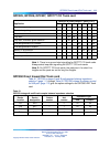
QPC414 Network card
Application
Pin connection
J3/S2 and J4/S1
T-1 facilities (including PRI/DTI),* channel service unit connect pins 1 and 2
(pin 1 is next to the white dot)
Note: Possible jumper locations for vintage B (for different styles/series):
J3—E11 or H11
J4—H17 or E7
Nortel Communication Server 1000
Circuit Card Reference
NN43001-311 01.04 Standard
Release 5.0 23 May 2008
Copyright © 2003-2008, Nortel Networks
.