


724 NT8D15 E and M Trunk card
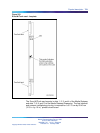
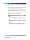
Figure 225 "E and M Trunk card - block diagram" (page 725) shows a block
diagram of the major functions contained on the E and M Trunk card. Each
of these functions is discussed on the following pages.
The NT8D15 E and M Trunk Card serves various transmission requirements.
The trunk circuits on the card can operate in either A or µ-Law companding
modes. The mode of operation is set by service change entries.
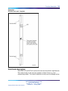
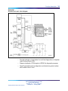
Figure 226 "E and M Trunk card - block diagram" (page 726) shows a block
diagram of the major functions contained on the E and M Trunk card. Each
of these functions is discussed on the following pages.
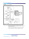
Figure 226 "E and M Trunk card - block diagram" (page 726) shows a block
diagram of the major functions contained on the E and M Trunk card. Each
of these functions is discussed on the following pages.
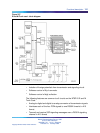
Common features
The following features are common to all circuits on the NT8D15 E and M
Trunk card:
•
Analog-to-digital and digital-to-analog conversion of transmission
signals.
•
Interfaces each of the four PCM signals to one DS30X timeslot in A10
format.
•
Transmit and receive SSD signaling messages over a DS30X signaling
channel in A10 format.
•
Ability to enable and disable individual ports or the entire card under
software control.
•
Provides outpulsing on the card. Make break ratios are defined in
software and down loaded at power up and by software commands.
Nortel Communication Server 1000
Circuit Card Reference
NN43001-311 01.04 Standard
Release 5.0 23 May 2008
Copyright © 2003-2008, Nortel Networks
.