


488 NT7D16 Data Access card
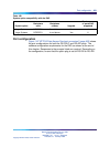
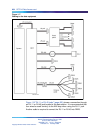
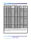
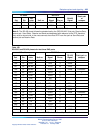
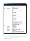
Table 192
RS-232-C and RS-422 pinouts for first three DAC ports
I/O cable RS-232-C
Pair Pin
Pair
color Unit no. Signal Pin no.
RS-422
Signal
Patch pair
or
octopus
1T
26
W-BL UNIT 0 TD0
2
RDA0
1R
1
BL-W RD0
3
RDB0
2T
27
W-O DTR0
20
SDA0
2R
2
O-W GND0
7
SDB0 Connector
3T
28
W-G DCD0
81
3R
3
G-W DSR0
6
4T
29
W-BR RI0
22
4R
4
BR-W CTS0
5
5T
20
W-S UNIT 1 TD1
2
RDA1
5R
5
S-W RD1
3
RDB1
6T
31
R-BL DTR1
20
SDA1
6R
6
BL-R GND1
7
SDB1 Connector
7T
32
R-O DCD1
82
7R
7
O-R DSR1
6
8T
33
R-G RI1
22
8R
8
G-R CTS1
5
9T
34
R-BR UNIT 2 TD2
2
RDA2
9R
9
BR-R RD2
3
RDB2
10T
35
R-S DTR2
20
SDA2
10R
10
S-R GND2
7
SDB2 Connector
11T
36
BK-BL DCD2
83
11R
11
BL-BK DSR2
6
Note 1: The RS-232 pinout follows the standard set by the QPC723 RILC.
Note 2: The RS-422 pinout follows the standard set by the QPC430 AILC (first pair: Receive Data;
second pair: Send Data). Receive and Send are designated with reference to the DTE; therefore,
they must be turned over in the cross-connect since most DTE have first pair as Send Data and
second pair as Receive Data.
Nortel Communication Server 1000
Circuit Card Reference
NN43001-311 01.04 Standard
Release 5.0 23 May 2008
Copyright © 2003-2008, Nortel Networks
.