


Configuring the SDI paddle board 805
terminal without having to stop the system. This is also used to perform a
parallel reload of the system software without affecting the operation of
the switch.
Connector pin assignments
The RS-232-C signals for port 1 are brought out on connector J1 and
the RS-232-C signals for port 2 are brought out on connector J2. The
pinouts of J1 and J2 are identical, so Table 311 "Connectors J1 and J2 pin
assignments" (page 805) can be used for both ports.
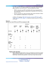
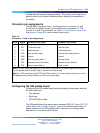
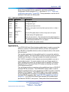
Table 311
Connectors J1 and J2 pin assignments
Pin #
Signal
Purpose in DTE mode
Purpose in DCE mode
1
CD Carrier detect (Note 1) Carrier detect (Not used)
2
RD Transmitted data Received data
3
TD Received data Transmitted data
4
DTR Data terminal ready Data terminal ready (Note 2)
5
GND Ground Ground
6
DSR Data set ready (Note 1) Data set ready
7
RTS Request to send (Not Used) Request to send (Note 2)
8
CTS Clear to send (Note 1) Clear to send
Note 1: In DTE mode the signals CD, DSR, and CTS are tied to +12 volts to signify that the port on
the SDI paddle board is always ready to transmit and receive data.
Note 2: In DCE mode the signals DTR and RTS are tied to +12 volts to signify that the port on the
SDI paddle board is always ready to transmit and receive data.
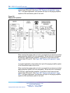
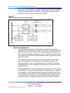
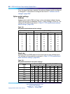
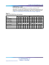
Configuring the SDI paddle board
Configuring the SDI paddle board consists of setting these option switches
for each serial port:
•
Port address
•
Baud rate
•
DTE/DCE/Fiber mode
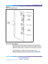
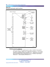
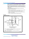
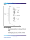
The SDI paddle board has seven option switches, SW 2–8. Figure 264 "SDI
paddle board option switch locations" (page 808) identifies the location of
option switches on the SDI paddle board. Instructions for setting these
switches are in the section that follows.
Nortel Communication Server 1000
Circuit Card Reference
NN43001-311 01.04 Standard
Release 5.0 23 May 2008
Copyright © 2003-2008, Nortel Networks
.