


1098 QPC513 Enhanced Ser ial Data Interface card
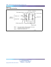
Synchronous port address space is the same as asynchronous port address
space. When selecting an address for the ESDI card, make sure that it does
not conflict with an address currently being used by an asynchronous card.
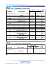
Table 447 "ESDI card address switch settings" (page 1098) shows the ESDI
card address switch settings.
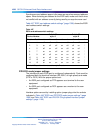
Table 447
ESDI card address switch settings
Device Number
Switch S2
style A
Switch S2
style B
Port 1 Port 2 1 2 3 4 1 2 3 4
01
off off off
on
off off off *
23
on
off off
on
off off
on
*
4
5
off
on
off
on
off
on
off *
6
7onon
off
on
off
on on
*
89
off off
on on on
off off *
10 11
on
off
on on on
off
on
*
12 13
off
on on on on on
off *
14 15
on on on on on on on
*
* Switch S2, position 4 is not used on style B cards.
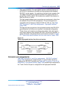
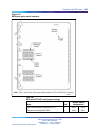
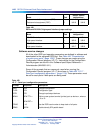
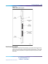
DTE/DCE mode jumper settings
The interface for each ESDI port is configured independently. Ports must be
configured both for electrical interface (RS-232-C or high-speed) and mode
(DTE or DCE). With the proper options set:
•
An ESDI port configured as DTE appears as a terminal to the user
equipment.
•
An ESDI port configured as DCE appears as a modem to the user
equipment.
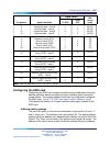
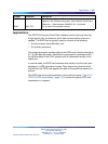
Interface options are set by installing option jumper plugs into the sockets
indicated in Table 448 "ESDI card DTE/DCE mode jumper settings" (page
1099) and Table 449 "ESDI card RS-232-C/high-speed interface jumper
settings" (page 1100).
Nortel Communication Server 1000
Circuit Card Reference
NN43001-311 01.04 Standard
Release 5.0 23 May 2008
Copyright © 2003-2008, Nortel Networks
.