


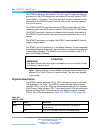

Physical description 925
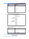
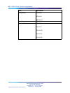
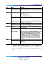
LED
State
Definition
On (Green) The NTAK79 2 MB PRI circuit card is in an active state.
ACT
Off The NTAK79 2 MB PRI is in a disabled state. The OOS
LED turns red.
On (Red) A red alarm state has been detected. This represents a
local alarm state of:
Loss of Carrier (LOS)
Loss of Frame (LFAS), or
Loss of CRC Multiframe (LMAS).
RED
Off No red (local) alarm.
On (Yellow) A yellow alarm state has been detected. This represents a
remote alarm indication from the far end. The alarm can be
either Alarm Indication (AIS) or Remote Alarm (RAI).
YEL
Off No yellow (remote) alarm.
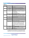
On (Green) 2 MB PRI is in loop-back mode.
LBK
Off 2 MB PRI is not in loop-back mode.
On (Red) The clock controller is switched on and has been disabled
by the software.
On (Green) The clock controller is switched on and is either locked to a
reference or in free run mode.
CC
Flashing (Green) The clock controller is switched on and attempting to lock
on to a reference (tracking mode). If the LED flashes
continuously over an extended period of time, check the
CC STAT in LD 60. If the CC is tracking this can be
an acceptable state. Check for slips and related clock
controller error conditions. If none exist, then this state
is acceptable, and the flashing is identifying jitter on the
reference.
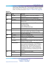
On (Red) DCH is switched on and disabled.
On (Green) DCH is switched on and enabled, but not necessarily
established.
DCH
Off DCH is switched off.
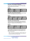
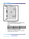
The NTAK79 uses a standard IPE-sized (9.5" by 12.5"), multilayer printed
circuit board. The faceplate is 7/8" wide and contains seven LEDs.
In general, the LEDs operate as shown in Table 377 "NTAK79 LEDs" (page
926).
Nortel Communication Server 1000
Circuit Card Reference
NN43001-311 01.04 Standard
Release 5.0 23 May 2008
Copyright © 2003-2008, Nortel Networks
.