


214 NT5D11 and NT5D14 Lineside T1 Interface cards
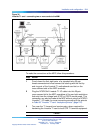
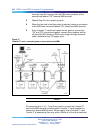
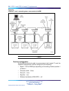
T1 connections
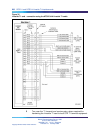
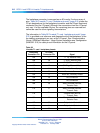
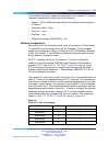
T1 signaling for all 24 channels is transmitted over P2 connector pins 1, 3,
9, and 11 as shown in Table 100 "Lineside T1 card - NT5D13AA Connector
pinouts" (page 213). Plug the DB15 male connector labeled "P2" into the
T1 link. T1 transmit and receive pairs must be turned over between the
Lineside T1 card and CPE equipment that is hardwired without carrier
facilities. If the Lineside T1 card is connected through T1 carr ier facilities,
the transmit and receive pairs must be wired straight through to the RJ48
at the Telco demarc, the CSU, or other T1 carrier equipment. The T1 CPE
equipment at the far end has transmit and receive wired straight from the
RJ48 demarc at the far end of the carrier facility.
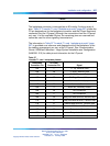
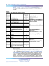
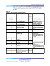
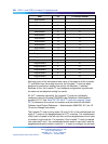
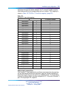
External alarm connections
P3 connector pins 3, 4, and 28 can be plugged into any external alarm
hardware. Plug the male DB9 connector labeled "P3" into the external
alarm. These connections are optional, and the functionality of the Lineside
T1 card is not affected if they are not made.
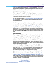
The MMI (described in detail in "Functional description" (page 391))
monitors the T1 link for specified performance criteria and reports on
problems detected.
One of the ways it can report information is through this external alarm
connection. If connected, the Lineside T1 card’s microprocessor activates
the external alarm hardware if it detects certain T1 link problems that it has
classified as alarm levels 1 or 2. See "Functional descr iption" (page 391) for
a detailed description of alarm levels and configuration. If an alarm level
1 or 2 is detected by MMI, the Lineside T1 card closes the contact that is
normally open, and opens the contact that is normally closed. The MMI
command Clear Alarm returns the alarm contacts to their normal state.
P3 connector pins 3, 4, and 28 can be plugged into any external alarm
hardware. Plug the male DB9 connector labeled "P3" into the external
alarm. These connections are optional, and the functionality of the Lineside
T1 card is not affected if they are not made.
Nortel Communication Server 1000
Circuit Card Reference
NN43001-311 01.04 Standard
Release 5.0 23 May 2008
Copyright © 2003-2008, Nortel Networks
.