


Configuring the QSDI paddle board 835
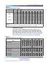
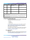
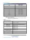
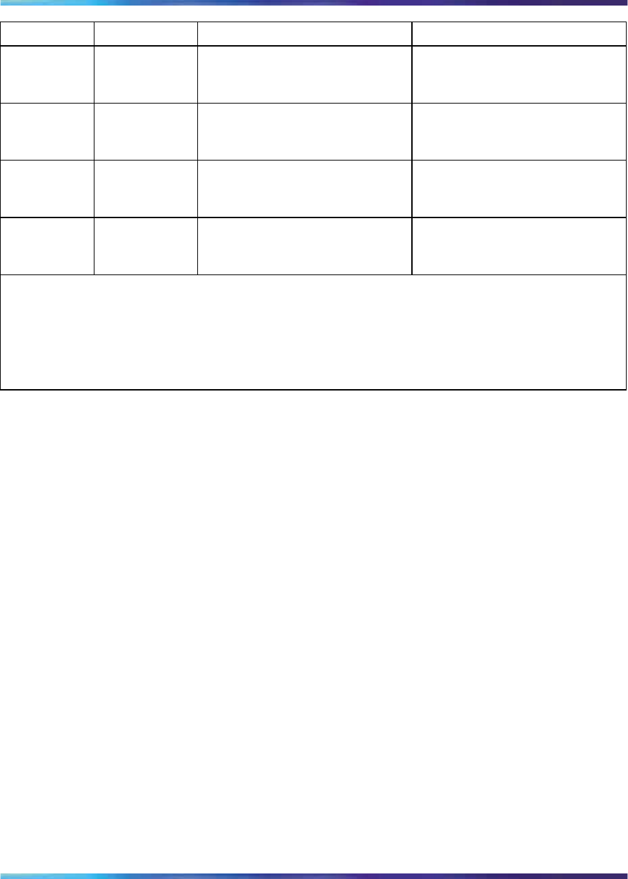
Pin #
Signal
Purpose in DTE mode
Purpose in DCE mode
5
G
N
D
Signal Ground Signal Ground
6
D
S
R
Data set ready (Note 1) Data set ready
7
R
T
S
Request to send (Not Used) Request to send (Note 2)
8
C
T
S
Clear to send (Note 1) Clear to send
Note 1: In DTE mode the signals CD, DSR, and CTS are tied to +12 volts to signify that the port on
the QSDI paddle board is always ready to transmit and receive data. This mode is set to connect
to a terminal device (DTE).
Note 2: In DCE mode the signals DTR and RTS are tied to +12 volts to signify that the port on the
QSDI paddle board is always ready to transmit and receive data. This mode is set to connect
to a modem device (DCE).
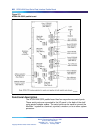
Configuring the QSDI paddle board
Configuring the QSDI paddle board to work in a Mer idian 1 system consists
of setting these option switches for each serial port:
•
Baud rate
•
Port address
•
DTE/DCE mode
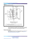
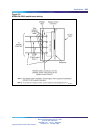
The QSDI paddle board has fourteen option switches, SW2–13, SW15-16.
Figure 273 "NT8D41BA QSDI paddle board" (page 832) identifies the
location of option switches on the QSDI paddle board. Learn how to set
these switches in the following sections.
Once the board has been installed, the system software must be configured
to recognize it. Instructions for doing this are found in the section titled
"Software service changes" (page 828).
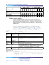
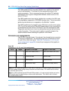
Option switch settings
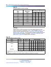
Baud rate
Switches SW13, SW10, SW11, and SW12 determine the baud rate for ports
1, 2, 3, and 4, respectively. See the settings for these switches in Table 327
"NT8D41BA baud rate switch settings" (page 836).
Nortel Communication Server 1000
Circuit Card Reference
NN43001-311 01.04 Standard
Release 5.0 23 May 2008
Copyright © 2003-2008, Nortel Networks
.